


FUNCTION CHARACTERISTICS
283
The operating mode may be selected by setting the
Mode67N
parameter, located inside the
Set \
Profile A (or B) \ Directional earth fault overcurrent-67N(Comp) \
Common configuration
menu.
The settable operating mode is
I
(module) or
I*cos
(projection).
For both the operating modes, the polarizing reference used for displacement measure of the resi-
dual current may be selected:
• Direct residual voltage - the measured
U
E
voltage is employed.
• Calculated residual voltage - the calculated
U
EC
voltage is employed, where the fundamental com-
ponent and phase are derived from the instantaneous values of the three input phase-to-neutral
voltages.
Therefore, for both operating mode, the displacement of the residual current phasor
I
ECH
or
I
ECL
and the residual voltage phasor (
U
E
or
U
EC
for direct/calculated residual voltage measurement type),
positive for lagging current compared with voltage (
Φ
E
=(
∠
U
E
-
∠
I
EC
,
Φ
EC
=(
∠
U
EC
-
∠
I
EC
.
The residual voltage measurement type may be selected by setting the
3Votype67N
parameter,
located inside the
Set \ Profile A (or B) \ Directional earth fault overcurrent-67N(Comp) \
Common
configuration
menu. The measurement type is
UE
(direct measure of residual voltage) or
UEC
(cal-
culated residual voltage).
For each of the four thresholds (
I
EDC
>,
I
EDC
>>,
I
EDC
>>>,
I
EDC
>>>>), the characteristic angle (
ϑ
E
>,
ϑ
E
>>,
ϑ
E
>>>,
ϑ
E
>>>>) may be adjusted (setting range 0…359° common for the three phases).
Similarly, the calculated residual current measurement is selected from the following two measures:
• Calculated residual current on side H - the calculated
I
ECH
current is employed, where the funda-
mental component and phase are derived from the instantaneous values of the three input pha-
se-currents.
• Calculated residual current on side L - the calculated
I
ECH
current is employed, where the funda-
mental component and phase are derived from the instantaneous values of the three input pha-
se-currents.
The residual current measurement type may be selected by setting the
ECtype67NC
parameter,
located inside the
Set \ Profile A (or B) \ Directional earth fault overcurrent-67N(Comp) \
Common
configuration
menu. The measurement type is
IECH
(side H) or
IECL
(side L).
For each of the four thresholds (
I
EDC
>,
I
EDC
>>,
I
EDC
>>>,
I
EDC
>>>>), the characteristic angle (
ϑ
E
>,
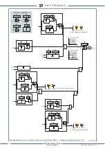
char-F67NC-mode.ai
I
ECH o
I
ECL
U
E
U
EC
Φ
E
o
Φ
EC
Thresholds (
I
EDC threshold
):
I
EDC
>,
I
EDC
>>,
I
EDC
>>>,
I
EDC
>>>>
[M(C)]∙(
I
EDC
>,
I
EDC
>>,
I
EDC
>>>,
I
EDC
>>>>)
Thresholds (
I
EDC threshold
):
I
EDC
>,
I
EDC
>>,
I
EDC
>>>,
I
EDC
>>>>
[M(C)]∙(
I
EDC
>,
I
EDC
>>,
I
EDC
>>>,
I
EDC
>>>>)
I
E
Φ
E
o
Φ
EC
U
E
U
EC
I
I∙cos
3Votype67NC
IECtype67NC
U
E
U
EC
I
ECH
I
ECL
67N(Comp)
I
L1H
,
I
L2H
,
I
L3H
I
L1L
,
I
L2L
,
I
L3L
Mode67NC
3V
o
I
I∙cos
3Votype67NC
IECtype67NC
U
E
U
EC
I
ECH
I
ECL
67N(Comp)
I
L1H
,
I
L2H
,
I
L3H
I
L1L
,
I
L2L
,
I
L3L
Mode67NC
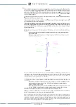
3V
o
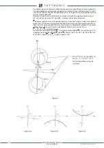
Operating characteristics of the earth fault overcurrent element - 67N(Comp)
with module operating mode (I)
Operating characteristics of the earth fault overcurrent element - 67N(Comp)
with projection operating mode ( I∙cos)
Characteristic axis
Characteristic axis
Half operating sector
(
β
E>
,
β
E>>
,
β
E>>>
,
β
E>>>>
)
Half operating sector
(
β
E>
,
β
E>>
,
β
E>>>
,
β
E>>>>
)
Half operating sector
(
β
E>
,
β
E>>
,
β
E>>>
,
β
E>>>>
)
Half operating sector
(
β
E>
,
β
E>>
,
β
E>>>
,
β
E>>>>
)
Characteristic angle
(
Θ
E>
,
Θ
E>>
,
Θ
E>>>
,
Θ
E>>>>
)
Characteristic angle
(
Θ
E>
,
Θ
E>>
,
Θ
E>>>
,
Θ
E>>>>
)
Trip sector
(toward line)
Trip sector
(toward line)
No trip sector
(toward busbar)
No trip sector
(toward busbar)
Operating characteristics of the ground directional overcurrent elements - 67N(Comp)
XMR-D EQUIPMENT MANUAL
Ed. 2.9 - 02/2021


