


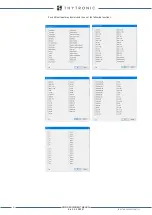


INSTALLATION
363
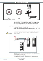
• Remove the two vertical frames for access the holes for the fixing screws; the frames are snapped
• Insert the device into the slot.
• Fit the device to the panel with four screws.
• Replace the vertical frames
Rack mounting
For mounting inside a standardized 19-inch system MAR adapter is required (available on request).
177 (4U)
101.6
482.6
465
6.3
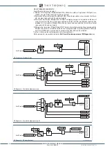
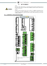
ELECTRICAL CONNECTIONS
Electrical connections should be made by referring to the connection diagram; in cases where cer-
tain of the circuits (communication, block, or others) are not used, the relevant connections must
remain open. Examples of connection diagrams are reported on Appendix to this manual.
For A1...A10, B1...B8, C1-C2 e Z1...Z8 screw terminals with following characteristics are available:
• Nominal cross section:
0.2 a 4 mm
2
(AWG 24...10) for single conductor
0.2 a 1.5 mm
2
for two conductors with same cross section
For the IN1F-1...10, IN2G-1...10, IN3H-1...10, OCD-1...6, OCE-1...10, OC1L-1...10 e OC1M-
1...10 connections, screw terminals with following characteristics are available:
• Nominal cross section:
0.14 a 2.5 mm
2
(AWG 26...16) for single conductor
0.14 a 0.75 mm
2
for two conductors with same cross section
For the X1...X7 (RS485 and blocks) connections, screw terminals with following characteristics are
available:
• Nominal cross section:
0.2 a 2.5 mm
2
(AWG 24...12) for single conductor
0.2 a 1.5 mm
2
for two conductors with same cross section
Devices must be installed by qualified personnel only.
No liability is accepted from Thytronic due to improper use.
CAUTION
Z
1
2
3
4
5
6
7
8
9
10
1
2
3
Y
A
B
NETWORK
X
1
2
3
4
5
6
7
TX
S1
S2
S4
Voltage Inputs
Aux Power Supply
Output Relays
7 OUTPUTS
ALWAYS EQUIPPED
Amperometric Inputs
Side H
Side L
Optional Modules
S1
S2
S4
S1 IN1F (7 INPUTS)
IN2G (7 INPUTS)
S2 alternately
{
OC2N (4 OUTPUTS)
IN3H (7 INPUTS)
S4 alternately
{
OC1L (4 OUTPUTS)
Example
ETHERNET RJ45
RS485
Rotor Earth Fault
64F
XMR-D EQUIPMENT MANUAL
Ed. 2.9 - 02/2021


