
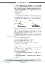


FUNCTION CHARACTERISTICS
169
inside the
Profile A (or B) \ Inadvertent energization-50/27 \
1st Pickup Element \ Setpoints
menu.
The status of the machine breaker is associated with a relay binary input; in particular the status
of open circuit breaker must be acquired (CB auxiliary contact that activates the logic input as the
switch is open).
The
52a
parameter must be assigned to the selected binary inputs inside the
Common parameters \
Binary inputs allocation
menu.
The protection element is blocked off whenever the VT supervision function are active, so that no
unwanted trip can arise if any fault on the VTs secondary circuits (break, fuse trip, etc) are de-
tect;
1
the Block functions enable from 74VT parameter (
74VT-BK-EN
)
are available inside the
Common Parameters \ VT supervision -74VT
menu.
Logical block (Block1)
If the
Block1
enabling parameter is set to
ON
and a binary input is designed for logical block (Block1),
the concerning element is blocked off whenever the given input is active.
2
The enabling parameter is
available inside the
Profile A (or B) \ Inadvertent energization-50/27 \
1st Pickup Element \ Setpoints
menu, while the
Block1
function must be assigned to the selected binary input inside the
Common
parameters \ Binary inputs allocation
menu.
Breaker failure (BF)
50-27 (IUE) threshold can be associated to BF (H) and BF (L) protection by activating the relative pa-
rameter in the matrices “Selection of function tripping for BF (H)” or “Selection of function tripping
for BF (L)” in relevant
BF
menus
3
:
• Set \ Profile A (or B) \ Breaker failure - BF side H
• Set \ Profile A (or B) \ Breaker failure - BF side L
Note 1 The exhaustive treatment of the VT and CT supervision function may be found inside the
CONTROL AND MONITORING
section.
Note 2 The exhaustive treatment of the logical block (Block 1) function may be found in the “Logic Block” paragraph inside
CONTROL AND MONITOR-
ING
section
Note 3 The common settings concerning the Breaker failure protection are adjustable inside the
Breaker Failure - BF
menu.
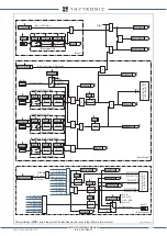
all-F50-27.ai
I
L1
I
L2
I
L3
U
L1
U
L2
U
L3
Block3
1st Pickup Element
Block1
CB
Block1
50+27
Trip
I
UE
>
Start
U
UE
>
Start
50+27 element
VT position
I
UE
>
U
UE
<
t
UE
t
UE-RES
General logic diagram of the inadvertent energization element - 50+27
XMR-D EQUIPMENT MANUAL
Ed. 2.9 - 02/2021


