6
2. New Features
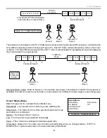
The rear panel i Link connectors on the back of this TV (see Figure 2-10) connect to hardware and software in the
DTV’s “Q box” to identify and react with other i Link devices. The speed of this i Link device is marked next to the
connector as 200 Mb/s.
Operation
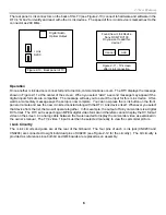
Once another i Link device is connected and turned on, communications occurs. The DTV displays the message
shown in Figure 2-11 at the center of the screen. When you select “Add”, a second message may appear if the
digital inputs formats are compatible. The message will ask you to select the input for this i Link device. After-
wards a momentary message says the setup is now complete. You can now press the i Link button on the front
panel or remote and see the new i Link device listed along with the DTV i Link device itself. Whenever you select
that device from the list, the two will operate together. In this example, the output of Sony camcorders is a digital
DV format. The DTV set is expecting an MPEG digital video format and therefore cannot display the DV format
video on the screen. An analog cable between the two is needed to display the camcorder video as explained in
the owner’s manual. The TV’s video 1 input must then be selected manually to view the camcorder picture.
i Link Circuitry
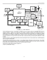
The i Link circuits and jacks are at the rear of the QI board. The four pins of each i Link jack (CN9203 and
CN9294) are connected to eight individual pins of IC9203 (see Figure 2-12 for the circuitry). The QI circuitry is
provided as reference since both QI and QM boards are replaced as an assembly.
Figure 2-10 - Back panel of TV
Digital Audio
Optical Output
i Link
S200
Figure 2-11 - TV screen
after i Link connection
Found new i Link Device
Sony DCR-TRV130
Do you want to add this
device?
Cancel
Add
Summary of Contents for KD-34XBR2 - 34" Hdtv Fd Trinitron Wega
Page 77: ...74 RA 5A Chassis Board Layout ...
Page 108: ...APPENDIX ...


