


7
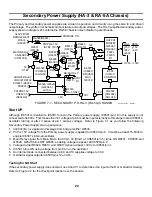
2. New Features
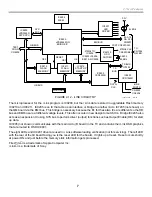
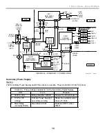
The microprocessor for the i Link program is IC9209, but the i Link data is stored in upgradable Flash memory
IC9210 and IC9211. IC9205 is an IC that acts as an interface or bridge to another micro IC7205 (not shown) on
the QM board via the EMI bus. This bridge is necessary because the B+ for these two ICs are different so the HB
bus and EMI bus are at different voltage levels. This often occurs in new design to match ICs. Bridge IC9205 also
acts as an expansion IC using SYS bus to perform driver (output) functions such as Output Enable (OE) for start
up data.
IC7205 (not shown) communicates with the main micro (B board) in the TV and contains the i Link OSD graphics
that are routed to OSD IC8801.
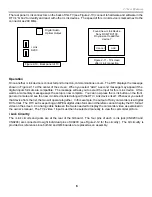
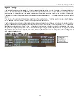
The eight LEDs and IC9201 driver are used in i Link software loading verification (not for servicing). The left LED
with the rear of the QI board facing you is the reset LED for the board. It lights up at reset. Reset occurs shortly
at power ON and just before the memory stick information gets processed.
Fire Wire
is a trademark of Apple Computer Inc.
i Link
is a trademark of Sony.
IC9213-5
OSC/
DIVIDER
IC9203
CXD1945R
IC9202
CXD3203R
IC9210
FLASH
MEMORY
IC9211
FLASH
MEMORY
IC9212
START-UP
MEMORY
IC9209
uPD3020D
MIPS CPU
IC9206
MEM.
IC9205
uPD82442GN
BRIDGE IC
IC9201
LED
DRIVER
TEST
CONN.
CN9205
CN9203
CN9204
27MHz TO:
IC9202,
IC9203,IC9205,
IC9210-2,IC9209
TO
CN7002
QM BD.
A1-A12,
D0- D15
CN9201
XRST CN9201/A13
27MHz CLK
CN9201/B25
X9203
49MHz
TS BUS
IC7205
TS
BUS
DATA/
CLK
SYS
BUS
HB BUS
CE0
RESET
CE1
OE
HB BUS
3.3V
8 LED's
iLINK
PORTS
QI BOARD
EMI BUS
9/4/01
1TVP12 1319
FIGURE 2-12 - iLINK CIRCUITRY
Summary of Contents for KD-34XBR2 - 34" Hdtv Fd Trinitron Wega
Page 77: ...74 RA 5A Chassis Board Layout ...
Page 108: ...APPENDIX ...