58
11. Video Process - HA-3 and RA-5A Chassis
DTV Tuner Processing for DTV Box Repair (HA-3 & RA-5A Chassis)
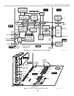
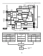
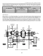
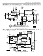
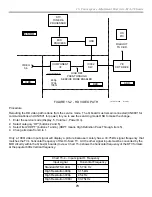
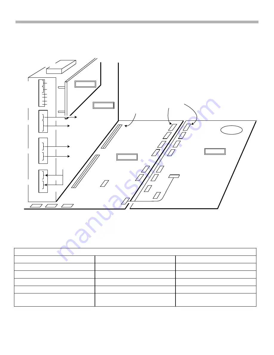
Refer to Figure 11-9 for the location of connectors and Figure 11-16 for the DTV tuner support signal diagram.
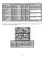
The DTV tuner needs various voltages for operation. They are easy to check at the Q box (CN7001). The DTV
tuner receives the 8VSB modulation and delivers that signal to Digital microprocessor IC7205.
IC7205 is one of three microprocessors in this TV that communicate with each other. Two are in the Q box and
the Main Micro is on the B board.
Chart 11-10 –Microprocessor Responsibilities
IC9209 MIPS CPU
IC7205 Digital Micro Processor
IC001 Main Micro
i Link operation
Memory Stick port access
Service mode & green user OSD
DTV video & audio processing
TV Protection / Diagnostics
DTV Tuner control
Power Supply Control
NTSC tuner control
Q box reset & Master
communications
1
2
3
4
5
6
7
8
1
2
3
4
5
6
7
1
3
4
5
7
1
2
3
5
6
7
6.5V
GND
5V
9V
GND
33V
1
A
B
GRAY
DIG TUNER
A
B
8
9
1
A
B
WHITE
1
11 11
11 11
BLK
FBT
CN7001
ALL
VOLT.
FROM
A BD.
CN6005
CN7402
CN8801
CN8601
PIN1 IS
CLOSEST TO
THE BACK
OF THE TV
25
32
1
1
FRONT OF TV
BACK OF TV
QM BD.
A BD.
D BD.
QI BD.
CN2001
CN4403
CN4404
CN001/
CN002/
CN3173
CN5501
CN3103
CN5505
CN6003
CN6503
CN6502
OSD CN004
VIDEO TO B BD.
AUDIO (RA-5)
TO B BD.,CN009
VIDEO INPUT
FROM B BD.
CN005
CN3174
CN5503
CN3171
CN6506
CN3170
CN6504
CN6001
CN6505
CN6501
SUB
MAIN
CN6005
FIGURE 11-9 - HA-3 CHASSIS CONNECTOR LAYOUT
38TVP12 1354
CN2002
CN2003
2 CH. AUDIO
(HA-3)
A C
A B
9/4/01
B BOARD
PLUGS INTO
CN2002 & 3
Summary of Contents for KD-34XBR2 - 34" Hdtv Fd Trinitron Wega
Page 77: ...74 RA 5A Chassis Board Layout ...
Page 108: ...APPENDIX ...

