24
8. Protection Block (HA-3 Chassis)
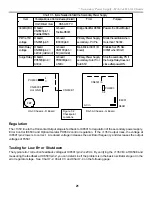
Chart 8-1 - Shutdown Causes
Stby
LED
Blinks
Protected areas Bd
Check
Point
Normal
Ck Pt
voltage
0 X
+200V OCP
(HV) / Over HV
D
Q8009/C
0.1Vdc
2 X
+135V OCP
D
CN6506/
pin 8
0V
3 X
+135V OVP
D
CN6506/
pin 7
0.1V
4 X
V Out
Loss
D
CN5505/
pin 7
0.78V
5 X (pix
blanked
- TV
remains
ON)
IK balance
C/A
/G2
adj
C Bd –
CN9001/
pin 8
3
pulses
in
vertical
interval.
6X
Q6.5V OVP &
OCP
A
D6021/
cathode
0Vdc
7X
H Out OCP
D
CN5505/
pin 8
0V
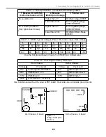
Front of TV
D Board
Q8009
FBT
CN6506
CN6504
CN6506
CN5503
CN5505
CN5501
8
10
1
Pin 1 of each connector
begins at this end
Figure 8-2
Protection Circuits
After the TV enters a protective state, the standby light blinks to identify one of seven problem sections. Each
section consists of not only the protected circuit (load) but also the sensing circuit that monitors the fault. A
description these seven sections consist of the sensing circuit itself so you know how the load is being protected
and a test for the load.
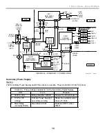
Standby light blinks 0 times – TV Shutdown
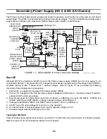
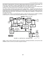
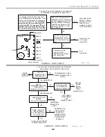
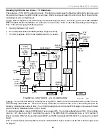
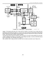
Refer to Figure 8-3 for the circuit description and Flow Charts A and B (Figures 8-4 and 8-5) for the testing
procedure.
Circuit – When the TV shuts down and the Standby light will not indicate the trouble area, five circuits are suspect:
•
200V OCP (HV Over current protection)
•
ABL voltage too LOW (Video Output Failure)
•
Excessive HV
•
Surge Relay did not energize
•
Shutdown Latch Circuit failure
1. 200V OCP - R8043 and Q8009 monitor the current on the +200 volt line. This 200-volt line supplies the High
Voltage Converter stage, which feeds the flyback transformer. The flyback generates HV, focus voltage and ABL
voltage. A short in the flyback or excessive high voltage will demand sufficient current to shut down the TV. When
the voltage across R8043 reaches 1.2Vdc, Q8009 outputs a HIGH that passes through D8003 to trigger the latch
formed by Q6530/Q6532. The latch grounds the voltage required to sustain relay driver Q6527 and the TV shuts
off. Since there is no connection to the Main Micro IC001, the standby LED will not indicate this failure.
2. ABL voltage - The ABL voltage from the flyback T8001 at pin 1 is monitored by IC8001. As the CRT draws more
current from the flyback’s HV output, the ABL voltage reduces. If this voltage drops to 0Vdc, IC8001 outputs a
HIGH for as long as the TV is powered ON. The HIGH passes through D8027 to trigger the Q6530/Q6532 latch
that finally shuts off the TV set.
3. Excessive HV - To shut down the TV when there is excessive HV, a winding of the FBT produces a voltage
proportional to the HV. This secondary AC voltage is rectified by D8014 and applied to protection latch IC8001.
Summary of Contents for KD-34XBR2 - 34" Hdtv Fd Trinitron Wega
Page 77: ...74 RA 5A Chassis Board Layout ...
Page 108: ...APPENDIX ...

