43
11. Video Process - HA-3 and RA-5A Chassis
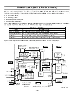
A board – The Y/C CRT Drive IC3101 converts the input video to RGB, mixes any OSD and outputs the combined
signal to the CRT on the C board.
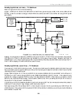
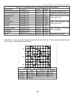
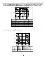
In the twin picture mode, the DTV picture or video 5 or 6 high resolution input will always appear on the left side
and never swap places. Video 5, 6 or a DTV station CANNOT be selected in the right picture.
DTV or
HD pix
Main pix
Figure 11-4 - Twin
Picture Mode with
Digital Input
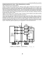
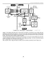
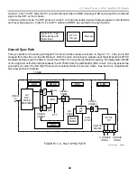
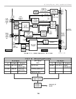
Overall Sync Path
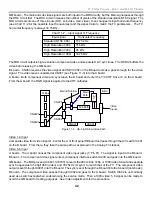
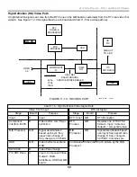
The sync paths for the analog and digital TV tuner and video inputs are shown in Figure 11-5. The sync is first
stripped from the video on the left B board. Both the main and sub sync signals input the QM board as NTSC
standard, but leaving is 33.75kHz to match that of the TV’s horizontal oscillator frequency. Normally switch IC006
on the right part of the B board just passes the 33.75kHz from the (QM board’s) MID circuit. IC6 only selects the
sub path sync when the HD High Pass mode is selected from the service mode. See the Conv. Adjustments
Overview section for details.
IC001
MICRO
IC3101
Y/C
A/V
SW./
VIDEO
PROCESS
A6
B6
A4
B4
MID
A8
B8
IC6
SW
A6
B6
H
V
H
V
H
V
H
V
VIDEO
1-6
IN
TUNER
MAIN
SUB
SUB
SYNC
V, H DRIVE
(D BD.)
CN005/
CN8601
CN8801/
CN004
B BD.
QM BD.
A BD.
FIGURE 11-5 - HA-3 SYNC PATH
42TVP12 1357
8/30/01
HD
PASS
3
4
2
CN001/
CN3020
CN3174/
CN5503
H DRIVE
(D BD.)
V
DTV
B BD.
B BD.
Summary of Contents for KD-34XBR2 - 34" Hdtv Fd Trinitron Wega
Page 77: ...74 RA 5A Chassis Board Layout ...
Page 108: ...APPENDIX ...

