95
21. RA-5A Chassis High Voltage Stage
High Voltage Stage (RA-5A Chassis)
HV Power Supply Start Up (Board level repairs)
As shown in Chart 21-1, the HV stage starts when enabled by three inputs.
Chart 21-1- HV Stage Inputs (for Starting)
Name
From
Checkpoint
1. +135Vdc D6104 / cathode (G Bd – Sec PS)
Q8035/ S (D Bd)
2. +12Vdc
12V Reg IC8004 / output (D Bd)
IC8008/1 (bottom) or
(CN8016/pin 1, 2)
3. H Drive
Video Process IC3006/pin 40
CN8006/pin 10
Once these three voltages are present, there is no reason the HV should not start unless the D board HV circuitry
is defective. See Testing for the procedure and location of the checkpoint connectors.
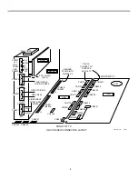
The HV stage can be tested for operation and level by measuring the sample of the HV at:
CN8016/pin 3 = 7.46Vdc. See Figure 21-2 for the schematic and “Testing” for connector locations.
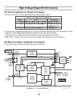
HV Block Description (Component level repairs)
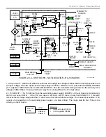
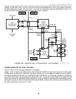
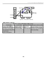
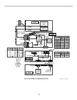
The HV Stage only has a few major blocks as shown in Figure 21-1.
Q8035
HV REG.
HV DIST.
BLOCK
Q8038
DRIVER
HV OUT
IC8006, 7
PROT.
IC8008
PWM
GEN.
IC8004
12V REG.
T8005
FBT
T8004
LOT
9
3
1
2
3
4
1
10
10
CN6106/
CN8013
CN3005/
CN8004
+135V
H DRIVE
IC3006/40
H DRIVE
+15V
+12V
+135V
ABL
CN3007/
CN8006
CN8022/
CN7304
CN8016
7.46V
200V
TO VIDEO
OUTPUT
CRT
R
G
B
C BD.
+135V
+135V
G BD.
7.46V
FIGURE 21-1 - RA-5 HV BLOCK
45TVP 1366
9/4/01
Summary of Contents for KD-34XBR2 - 34" Hdtv Fd Trinitron Wega
Page 77: ...74 RA 5A Chassis Board Layout ...
Page 108: ...APPENDIX ...

