45
11. Video Process - HA-3 and RA-5A Chassis
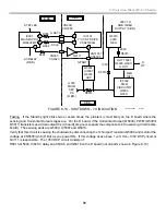
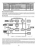
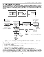
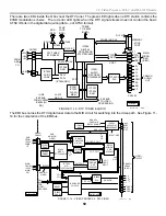
NTSC Twin View (Picture with Picture) Video Path
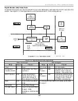
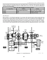
When the Twin View (Picture with Picture) feature is selected, two pictures appear on screen side by side. Two
video sources are chosen and two video paths are used to support these pictures. The main picture starts at the
left side when the pictures are the same size. With the remote, one picture can be made larger than the other
can. The larger picture will always take the main picture path with two NTSC inputs so video paths are switched
as necessary. Picture switching is done at the MID Process (QM board) and the Component I/F and Main Sw ICs
on the B board.
The combined picture leaves the MID process with a new horizontal frequency to match the TV as well. An OSD
IC buffers the component video before leaving the QM board. The component video and sync pass through the
B board and enter the Y/C CRT Drive IC on the A board. The Y/C CRT Drive IC output is RGB that goes into the
C board and CRT cathodes.
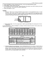
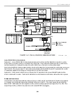
Main and Twin Mode Video Troubleshooting
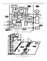
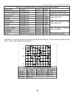
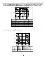
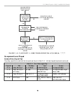
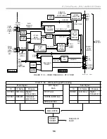
Because of the switching in the Twin mode, we can use the Twin Mode user operation to isolate the problem to a
board. Use Figure 11-8 for identifying a video problem using two NTSC signals, and Figure 11-13 for an ATSC
signal problem. With the suspected board in mind, you can use your scope to prove the problem is in the
suspected board by checking for video signals at chassis connectors (signal tracing).
OSD
DRC
PROCESS
ANALOG
VIDEO
PROCESS
IC002
SW.
ANALOG
TUNER
CRT
DRIVE
A/V
SW.
MAIN
SW.
MID
PROCESS
MAIN
PIX
RGB OUT
TO C BD.
VIDEO
1-6
VIDEO
2
COMBINED PIX
HD BD.
QM BD.
U BD.
HD BD.
B BD.
A BD.
COMPONENT
I/F, SUB SW.
SUB
PIX
MAIN
SUB
MAIN
SUB
9/4/01
9TVP12 1326
MID
MICRO
MN SB
SW.
LARGER PIX IS
ALWAYS MAIN
SUB
MAIN
SUB
MAIN
FIGURE 11-7 - NTSC ONLY TWIN VIEW VIDEO PATH
Summary of Contents for KD-34XBR2 - 34" Hdtv Fd Trinitron Wega
Page 77: ...74 RA 5A Chassis Board Layout ...
Page 108: ...APPENDIX ...

