


64
13. Firmware Upgrade
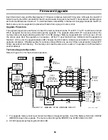
3. IC7205 (QM Bd) uses TXD and RXD to communicate with Main Micro IC001 (B Bd). When IC7205 requests
a memory upgrade operation, IC001 must interrupt the normal TV operation.
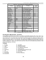
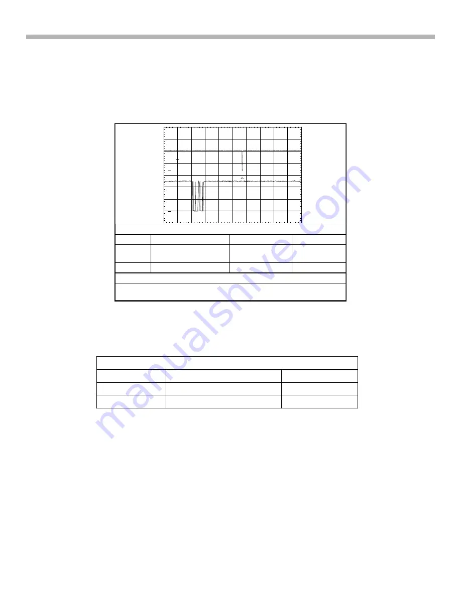
Waveform 13-1 shows typical Q box to Main Micro IC001 (B Bd) bi-directional communications. Normally
there is only periodic communications and then only when needed. This waveform was taken when changing
into a DTV station (channel up command). In the waveform sequence, notice that the Main Micro starts the
communications (ch 2) and the Q board micro replies afterwards (ch 1). When changing into NTSC stations
that do not require the Q box to select a station, there is no (ch 1) reply. Note that the output of the Q box is
5Vp-p and the reply signal from IC001 is only 3Vp-p.
PM3394, FLUKE & PHILIPS
CH1!2.00 V=
CH2!2.00 V= MTB2.00ms- 5.82dv ch1-
1
2
T
Ch 1
Ch 2
Waveform 13-1 – Microprocessor Communications* QM – B Board
Channel
Signal Name
Location
Vp-p
1
RXD to Main Micro
IC001 (B Bd)
CN8801/pin B11
3Vp-p
2
TXD
CN8801/pin A11
5Vp-p
Time Base = 2msec/div.
* Taken when channel changing into a DTV station. When changing to
another NTSC station, RXD signal (ch 1) from the Q box is not present.
4. Main Micro IC001 displays “Memory Upgrade Mode” on the screen.
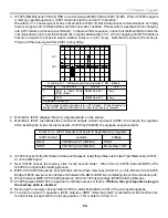
5. Main Micro IC001 then blanks the screen and outputs a Grant and reset (XRST) line to begin the upgrade.
After resetting the Q box microprocessors, IC7205 and IC9209, the upgrade sequence starts.
Chart 13-2 - IC001 Outputs to Q board to begin Memory Upgrade
IC001 Output
Location
Voltage
Grant
CN8801/pin A1 (QM Bd)
HIGH
XRST
CN7201/pin A2 (QM Bd)
Momentary LOW
6. IC7205 checks for the first folder of data and if present, loads these files into the two Flash Memories (IC7201-
2) on the QM board.
7. Next IC7205 checks the memory stick for the second folder. When found, IC7205 instructs MIPS CPU
IC9209 to complete the loading process.
8. MIPS CPU IC9209 loads the second folder into two flash memories (IC9210-1) on the QI board via IC9205.
Bridge IC9205 serves as an interface IC between the EMI and HB bus completing the communications path.
9. When finished, MIPS CPU IC9209 sends an OK to IC7205 using bridge IC9205 and the EMI bus.
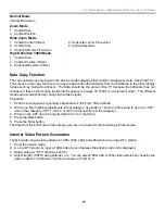
10. IC7205 pulses LED D7204 in a pattern to indicate success or failure.
If failure, the cycle repeats as long as
the memory stick is inserted
.
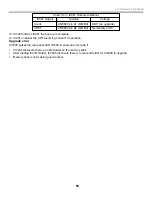
11. Removing the memory stick permits IC7205 to inform Main Micro IC001 of the successful upgrade.
12. To return to normal TV operation, IC001 outputs a XRST momentary LOW to restart the Q box but this time
the Grant line is kept LOW for normal operation. This is listed in Chart 13-3.
Summary of Contents for KD-34XBR2 - 34" Hdtv Fd Trinitron Wega
Page 77: ...74 RA 5A Chassis Board Layout ...
Page 108: ...APPENDIX ...