101
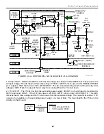
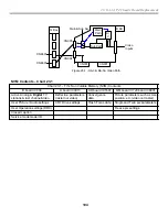
22. RA-5A Chassis Video Process
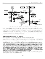
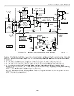
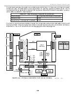
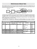
The AD board generates the pattern as an RGB signal (CN3013/pin 1-3) that is sent to Video Processor
IC3006 (A board). The RGB pattern is accompanied by a Ys switching signal from CN3012/pin 20. The Ys
control signal from the AD board is normally 0Vdc, but goes to 5Vdc when the Flash Focus pattern or conver-
gence pattern is called for. See Chart 22-1.
Chart 22-1 - Video Process(or) Output Vs Ys control Input
Picture Output
Ys input from CN3012/pin 20 AD board
Normal picture
0Vdc
Flash Focus or Convergence crosshatch
5Vdc
The 5Vdc Ys input signal tells IC3006 to replace the normal video path with the RGB pattern from the AD
board when HIGH. This also implies that a defect on the AD board can stop the normal picture and leave a
blank screen. The PJ TV set will still run normally without the AD board plugged in.
SUB
TUNER
MAIN
TUNER
VIDEO
PROCESS
P
B
- A
2
P
R
- A
3
Y - A
1
H
S
- B
3
V
S
- B
4
Y - A
5
P
B
- A
6
P
R
- A
7
H
S
- A
8
V
S
- B
8
Y - A
3
P
B
- A
4
P
R
- A
5
H
S
- A
6
V
S
- B
6
B9 B6
Y - C15
P
B
- C16
P
R
- C17
H
S
- C18
V
S
- C19
SUB
TUNER
VIDEO
MAIN
TUNER
VIDEO
V
1
= A
1
Y
1
= A
2
C
1
= A
3
Y = A15
P
B
= A16
P
R
= A17
VIDEO 1 VIDEO 6
INPUTS
R = 2
G = 3
B = 5
CN3011/PINS
CN001
CN002
CN3020
CN3022
CN003
CN7001
CN7402
CN8801
CN8601
RGB
C BOARDS
U BD.
B BD.
Q BOX
A BD.
B9
B6
CN005
CN004
SUB
MAIN
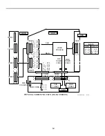
FIGURE 22-2 - PHYSICAL VIDEO/SYNC PATH (RA-5A CHASSIS)
50TVP12 1363
9/4/01
A
1
B
1
B
11
A
11
A
1
C
1
A
25
C
31
A
32
C
32
B
1
A
1
B
11
A
11
B
1
A
11
B
11
A
1
B
1
A
11
B
11
A
1
A
1
C
1
A
1
B
1
B
25
32
1
25
1
A
31
Summary of Contents for KD-34XBR2 - 34" Hdtv Fd Trinitron Wega
Page 77: ...74 RA 5A Chassis Board Layout ...
Page 108: ...APPENDIX ...

