100
22. RA-5A Chassis Video Process
Video Process (RA-5A Chassis)
The Video processing for the projection TV chassis is almost identical to the HA-3 chassis. The difference is the
A board. An AD board is a plug-in to the A board for convergence operation and the output connector is a different
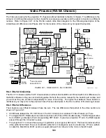
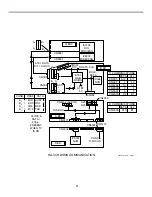
number. Refer to Figure 22-1 of the RA-5A overall video block diagram for the following description of the
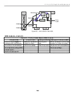
similarities and differences and Figure 22-2 for the location of the video and sync signal checkpoints.
HA-3 / RA-5A Similarities
The HA-3 TV chassis and RA-5A TV chassis share an almost identical QM and B board with minor differences to
the NVM software so they are not interchangeable. Refer to the service manual for the board’s part number and
you will see they are stocked independently for ease of servicing. The signal flow between these boards is
identical so you may refer to the previous Video Process description in the HA-3 section of this training manual.
HA-3 / RA-5A Differences
The A board is very different between these two sets. The two differences that pertain to the video section are
shown in Figure 22-1:
•
IC3006 was labeled the Y/C CRT Drive in the HA-3 chassis, but is labeled “Video Process (or)” here.
•
The single CN3011 RGB output connector branches out to three CRTs simultaneously. The RGB signal wires
from CN3011 go directly to their corresponding CRT board. In previous projection TV sets, the RGB signals
passed through the C boards in series
•
The projection TV’s A board has a plug-in registration (convergence) AD board. This board produces either
video patterns for Flash Focus or crosshatch patterns for convergence (service mode only). When a pattern
is called for, Main Micro IC001 sends a request (data path not shown) to the micro in the AD board.
CB
BD.
9/4/01
48TVP12 1360
ANALOG
TUNERS
IC002
SW.
Q9, Q11, Q13
MIXER
IC7806,
IC7807
DRC
PROCESS
IC8801
OSD
IC001
MAIN MICRO
IC7205, IC7603
DTV TUNER
AND PROCESS
IC205
MAIN SW.
IC8601
IC8703, IC8902
MID PROCESS
IC201,IC202,
IC204,IC207
ANALOG VIDEO
PROCESSING
IC401
A/V
SW.
IC200
COMPONENT
INTERFACE I/F
IC201 SUB SW.
NTSC
OR
HD
INPUT
CN4001/
CN003
NTSC
SUB
PATH
MAIN SIGNAL PATH
NTSC INPUT/ PIP
NTSC
MAIN
PATH
NTSC
OSD
OSD
MAIN
CN002/
CN3022
CN8601/
CN005
OSD
CN8801
CN001/
CN3020
VIDEO
5,6
VIDEO
1,3,4
CN008/
CN1200
HD
(33.75kHz)
VD (60Hz)
HB BD.
QM BD.
B BD.
U BD.
C BD.
A BD.
VIDEO
2
SUB
MAIN
A1-3
A5-7
C
11
13
C
15
17
HD
VIDEO
5,6
*
*
SERVICE MODE
ENABLED PATH
A3-5
A7-9
B
6
B
9
1, 3, 5
A9
MN-SB-
SW.
CG
BD.
CR
BD.
IC3006
VIDEO
PROCESS
AD
BD.
1,
2,
3
20
D
REG
YS
RGB
CN3012/
CN1601
CN3013/
CN1602
CN3011
CRT B
CRT G
CRT R
FIGURE 22-1 - VIDEO BLOCK - RA-5 CHASSIS
Summary of Contents for KD-34XBR2 - 34" Hdtv Fd Trinitron Wega
Page 77: ...74 RA 5A Chassis Board Layout ...
Page 108: ...APPENDIX ...

