


41
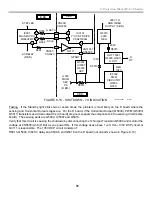
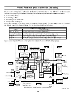
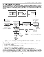
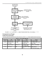
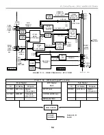
11. Video Process - HA-3 and RA-5A Chassis
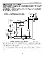
Digital TV station Input
QM board – Selecting a digital TV channel requires the communications of the Main Micro IC001 (B board) and
Digital Processor IC7205 (QM board - not shown). At each channel up or down command, the Main Micro IC001
(B Bd.) asks Digital Processor IC7205 if the next station is an active DTV station. If the next station is digital, the
reply contains the channel number (IC001 displays channel numbers). Main TV Micro IC001 instructs IC7205
(QM board) to receive that DTV channel.
Digital TV station processing is then entirely performed on the QM board. The DTV tuner receives the station
while its circuitry (IC7205, IC7603) converts the digital signal to final component video form with two or six chan-
nel audio output. OSD IC8801 buffers the component analog video before sending it to the B board.
Previously, the TV’s Main Micro generated the OSD menu and channel numbers. IC8801 now generates all the
TV menu graphics from the QM board, but the Main Micro (B board) still makes the green channel numbers and
controls the service mode display.
B board – The menu OSD from IC8801 (QM board) and channel number/service mode OSD from the Main Micro
IC001 are combined by Q9, Q11 and Q13 and sent to the A board. The DTV’s component video passes through
switch IC002 and enters the A board.
A board – Both the OSD information (if any) and the DTV station’s component video enter the Y/C, CRT Drive
IC3101 to be merged. The combined output leaves as RGB to the CRT on the C board.
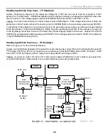
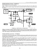
Analog TV station Input
A board – Both the main and sub analog tuners are mounted on the A board. Their composite video outputs are
sent to the A/V switch on the B board.
B board – A/V switch IC401 chooses the signal path for the main and sub tuners. The main tuner signal may
either enter the main path or be switched into the sub path. The main path leaves IC205 on the B board for the
QM board (Q Box). The sub path leaves IC200 on the B board for the QM board (Q Box). When a single analog
picture is selected, the main signal path into the DRC circuitry on the QM board is always taken, no matter which
tuner originates the signal.
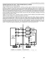
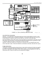
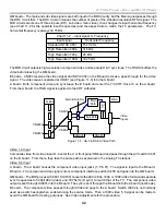
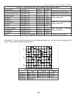
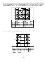
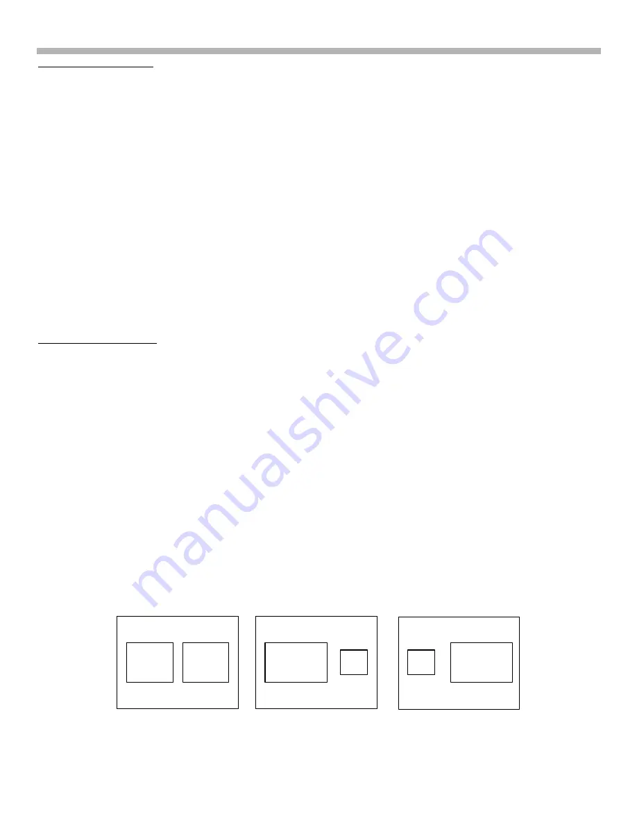
In the Twin View picture mode (Figure 11-2), both main and sub paths are used to produce two pictures on the
screen side by side. The main picture from IC205 is positioned on the left side by the MID circuit when both
pictures are the same size (Figure 11-2 a) or the left picture is the larger picture (Figure 11-2 b). When the picture
on the right becomes the larger (Figure 11-2 c), the MID process reverses the position so the larger picture always
comes from the DRC process (main signal path) via IC205. Earlier in the signal path, IC200 and IC205 switch the
input signals to keep the same station at the same position on the screen. The main (IC205) and sub (IC200) IC
switches are inversely controlled by a single “MN SB SW” line from the MID micro on the QM board. A slight delay
occurs when the right picture just begins to become larger, allowing the MID circuit to switch positions. The
picture freezes for a moment until both switches have been made, then the frame continues to increase in size.
Figure 11-2 - Twin Picture Mode, Analog Inputs
Main
pix
IC205
Sub
pix
IC200
Main pix
from IC205
S
Main pix
from IC205
S
a
b
c
Summary of Contents for KD-34XBR2 - 34" Hdtv Fd Trinitron Wega
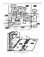
Page 77: ...74 RA 5A Chassis Board Layout ...
Page 108: ...APPENDIX ...