42
11. Video Process - HA-3 and RA-5A Chassis
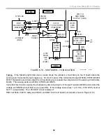
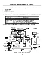
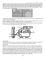
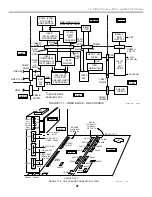
QM board – The main and sub video signals are both input to the MID circuitry, but the Main signal passes through
the DRC circuit first. The DRC circuit increases the number of pixels of the standard resolution NTSC signal. The
MID circuit selects one of three inputs (DTV, sub video, main video), then changes its input horizontal frequency
(see Chart 11-2 for the possible input frequencies) and the aspect ratio to match the TV parameters. The TV
horizontal frequency is always 33.75kHz.
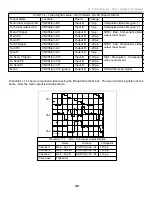
Chart 11-2 – Input signal H. Frequency
Input signal
Horizontal Frequency
Standard NTSC 480i
15,734 Hz
High Resolution 480p
31.5kHz
High Resolution 720p
45.kHz
High Resolution 1080i
33.75kHz
The MID circuit output is high-resolution component video and separate H & V sync lines. The OSD IC buffers the
video before leaving the QM board.
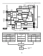
B board – CN004 receives the video signal and SW IC002 on the B board acts as a pass-through for the video
signal. The video leaves unaltered at CN001 (see Figure 11-3) into the A board.
A board - Both component video and sync leave the B board and enter the Y/C CRT Drive IC on the A board.
From the A board, the RGB signal is applied to the CRT cathodes.
Q Box
CN001
CN001
Sub Path
Main
Path
A/
V
B Bd.
Main & Sub Sw
CN005
CN004
Video
Inputs
CN8801
CN8601
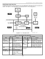
Figure 11-3 - HA-3 & RA-5A Video Path
Video 1-4 Input
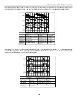
Composite video from video inputs 1-4 enter the U or front panel HB board and pass through the A/V switch IC401
on the B board. From there, they take the same path as explained in the Analog TV stations.
Video 5-6 Input
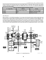
U board – The U board houses the component video input jacks (Y, Pb, Pr). The signal is input to the B board.
B board – The component video signal enters component interface switch IC200 and goes into the QM board.
QM board – The MID process (IC8601, IC8703) converts the 480i, 480p, 720p or 1080i video format and separate
sync frequencies to 540p/1080i (video) and 33.75kHz (H sync) to match that of the TV. The component video
output is sent through IC8801 into the B board. The sync is sent through the B board into the A board (not shown).
B board – The component video passes through IC002 and goes to the A board. Switch IC002 is not normally
used as a switch except when enabled using the service mode. Then a 1080i video 5, 6 signal can be made to
avoid the QM board for testing purposes. See Video Adjustments for the procedure.
Summary of Contents for KD-34XBR2 - 34" Hdtv Fd Trinitron Wega
Page 77: ...74 RA 5A Chassis Board Layout ...
Page 108: ...APPENDIX ...

