23
8. Protection Block (HA-3 Chassis)
Protection Block (HA-3 Chassis)
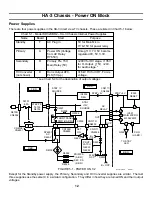
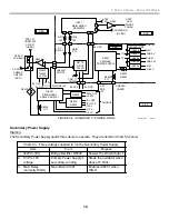
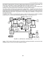
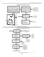
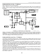
Refer to Figure 8-1
for the following overview of the protection circuits. When a failure occurs, this TV will protect
the remainder of its circuitry in one of the following ways:
•
TV shutdown (AC relay is turned off);
•
TV Latched OFF (AC relay is held off); or
•
A dark picture (no RGB signal to the CRT cathodes).
When Main Micro IC001 places the TV in a protective state, IC001 also indicates the cause by blinking the
Standby LED a number of times, pauses, and then repeats the same count.
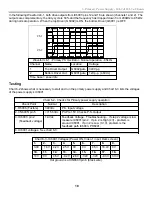
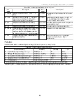
There are seven protected areas summarized in Chart 8-1
.
Chart 1 also lists the signal that triggered the protec-
tion. If no signal triggered the protection, suspect Micro IC001 on the B board and the latch transistors (Q6522/
Q6530) on the D board of causing the TV shutdown. Figure 8-2 shows the location of Chart 8-1’s protection
signal checkpoints.
V LOSS
POWER OFF
LATCH
+135V
OCP
IC3101
Y/C CRT
DRIVE
Q6.5V
OCP/
OVP
IC001 MAIN MICRO
A25 C25
C24
C26
B19 A20
8
7
+135V
OVP
8
7
8
+200V
OCP
+135V
OCP
(H.OUT)
CN001/
CN3020
OVP
OCP
S
DATA
STANDBY LED
SCLK
CN002/
CN3022
CN3101/
CN9001
IK
PULSES
CN6506/
CN3171
CN6504/
CN3170
CN3103/
CN5505
AC
RELAY
OVP
OCP
NUMBER OF TIMES
THE STANDBY
LIGHT BLINKS
X
B BD.
A BD.
C BD.
D BD.
AC RELAY
POWER
ON/OFF
0X
3X
2X
0X
6X
5X
4X
7X
1
D BD.
ABL
Q8008
0X
9/4/01
20TVP12 1338
EXCESS
HV
FIGURE 8-1 - PROTECTION BLOCK
0X
Summary of Contents for KD-34XBR2 - 34" Hdtv Fd Trinitron Wega
Page 77: ...74 RA 5A Chassis Board Layout ...
Page 108: ...APPENDIX ...

