50
11. Video Process - HA-3 and RA-5A Chassis
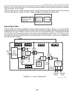
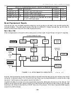
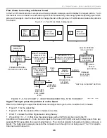
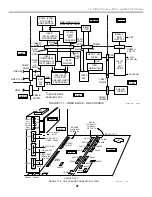
High Definition (HD) Video Path
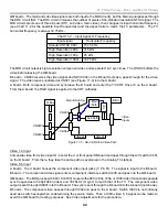
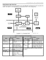
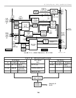
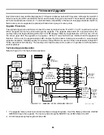
A high definition signal can come from the DTV tuner in the QM board or externally from the TV’s rear video 5 or
video 6. See Figure 11-10 for signal flow to each board and Chart 11-5 for a video path list.
HD
PIX
IC002
SW.
Y/C
CRT DRIVE
COMPONENT
I/F
OSD
MID
PROCESS
DTV
TUNER &
PROCESSOR
HD INPUTS
480p
720p
1080i
B BD.
QM BD.
A BD.
U BD.
VIDEO
5,6
RGB OUT
TO C BD.
8/30/01
10TVP12 1328
HIGH DEF
PASS-THROUGH
SERVICE MODE ENABLED
FIGURE 11-10 - HD VIDEO PATH
Chart 11-5 - High Definition Video Signal Path
Video 5 or 6 Input
DTV Air Signal
Stage
Board
Purpose
Stage
Board
Purpose
Input
U
Input
DTV Tuner
QM
DTV Reception
Component
Interface IC200
B
Video buffer; H & V Sync
extraction
DTV
Process
QM
Decodes one of 18 ATSC
formats. Input = Antenna
Outputs = component video.
MID Processor
QM
Signal determination
based upon sync freq.;
aspect ratio change; H
freq. change to 33.75kHz
MID
Processor
QM
Signal determination based
upon sync freq; aspect ratio
change; H freq. change to
33.75kHz. Combines pix.
OSD
QM
Video buffer, User Menu
OSD
SW IC002
B
Video Pass through
Y/C CRT Drive
A
Input = Component Video.
Output = RGB.
Adds Menu OSD from QM
board.
Combined with the Video 5 or 6 picture by the MID
Processor
Summary of Contents for KD-34XBR2 - 34" Hdtv Fd Trinitron Wega
Page 77: ...74 RA 5A Chassis Board Layout ...
Page 108: ...APPENDIX ...


