13
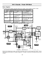
5. HA-3 Chassis - Power ON Block
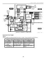
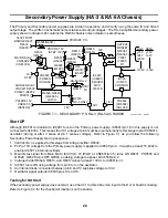
Each power supply is turned ON in the order listed. The standby power supply is operational when the TV is
plugged into AC. When the TV is powered ON, the second and third supplies are turned ON one after the other.
These supplies power the horizontal stages. Finally, the fourth (HV) power supply is turned ON after the horizon-
tal output transformer develops scan (AFC pulses are used). The HV power supply is not shown on Figure 5-1,
but knowing when the HV is powered ON is important for troubleshooting.
Standby Power Supply
When the TV is plugged in, the standby power supply outputs three voltages: +15V, +7V and +5V. A small
transformer develops the +15V and +7V. The +7V is regulated down to +5V to power the Main MicroIC001.
Primary & Secondary Power Supplies
Before power ON can occur, the front panel master ON/OFF button (S01 on the HA board) must be pressed in.
This latching switch behind the button supplies the AC relay (RY6501) with standby 7V. Pressing the switch again
would unlatch the switch and the set would shut OFF.
Power ON can be activated either from the remote control or when the front panel button is latched in. The
second half of front panel switch S01 (not shown) grounds the power ON input to Main Micro IC001. IC001
powers ON the TV by turning on relay driver Q6527. Q6527 grounds one end of RY6501 relay coil and momen-
tarily turns on Q2006 via C2039. Q2006 supplies a 15V to AC relay RY6501 because a relay requires
more voltage to close the contacts than to hold them closed, especially if the AC input voltage is below normal at
that time. Once RY6501’s contacts close, D6730 is powered and 340V is applied to the Primary and Secondary
power supplies.
Primary Power Supply
Starting
This primary power supply only needs 340Vdc from the bridge rectifier D6530 to start up and run.
Output Voltages
The Primary Power Supply outputs low voltages labeled “Sub” and “Q” voltages. The Q voltages go to the Q box
and the Sub voltages are distributed to the TV for operation. The Sub and Q voltages may be checked at the
board’s connector as shown in Chart 5-2.
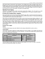
Chart 5-2 – Primary Power Supply Output Voltage Checkpoints
Output
Checkpoint
Output
Checkpoint
Sub 12V
CN6002/pin 1
Q6.5V
CN6005/pin 1, 2
Sub 9V
CN4402/pin 7 or CN3020/pin C4, C5
Q9V
CN6005/pin 6
Sub 5V
CN3020/pin C6, C7
Q5V
CN6005/pin 5
Sub 3.3V CN3020/pin C2, C3
The most important output voltage from the primary power supply is the “Pri Pre 15V” output. This volume
starts the Secondary power supply on the D board.
Summary of Contents for KD-34XBR2 - 34" Hdtv Fd Trinitron Wega
Page 77: ...74 RA 5A Chassis Board Layout ...
Page 108: ...APPENDIX ...

