19
6. Primary Power Supply - HA-3 & RA-5a Chassis
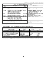
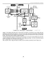
Chart 6-4 - IC6001 (MCZ3001D) Pin Description
Pin -
Name
Description
Pin -
Name
Description
1 - Sense ON/OFF input for the IC. IC ON = 1.5-
7Vdc.
8 – VC1
Power for IC. Input voltage limits = 15.6V
– 33V
2 – F/B
Feedback control voltage for regulation.
Needs bias current feed of 80uA min.
Open circuit triggers IC shutdown.
9 - OCP
When input voltage reaches 0.2Vdc, the
IC momentarily enters high freq, low
voltage output. Max = 5Vdc
3 - Ct
Determines Oscillator minimum freq
10 – VC2 10.5dc Output (regulated from VC1) & low
driver (pin 12) pwr.
4 – Rt
Determines Oscillator minimum freq
14 - VB
10.5dc Input for high driver (pin 16).
6 - Timer
External cap sets delay time to enter high
freq, low voltage output (protect state).
After four entry’s, the osc stops but can
be reset by removing Vcc (pin 8) voltage.
15 - VS
Reference for high side driver.
7 - SS
External cap determines initial start freq.
(200kHz in this TV).
18 - VD
Start up voltage for VC1, low & high
drivers internal to the IC. Max =
600V/12ma
Protection
See Chart 6-5 below. IC6001 stops operating and enters a protective stage when:
Chart 6-5 - IC6001 enters a protective state
Protection Cause
Location
Normal
Trip
1. Input V Sense input voltage too high
IC6001/pin 1
3V
8.3V
2. Primary PS Output too high
IC6001/pin 8 (VC1)
15Vdc
33Vdc
3. No regulation feedback (error voltage) *
IC6001/pin 2
1.86Vdc
0V (open)
4. Excessive Driver current(Q6001,2)
IC6001/pin 9
0Vdc
+0.2Vdc
5. IC temperature
Diode Internal to IC6001
?
155 C
* IC Output does not stop. Oscillator output changes from continuous normal operation to output bursts
RESET IC6001 = Unplug the AC line cord, (or shut off the TV if you can determine that) and wait 10 seconds.
Summary of Contents for KD-34XBR2 - 34" Hdtv Fd Trinitron Wega
Page 77: ...74 RA 5A Chassis Board Layout ...
Page 108: ...APPENDIX ...


