89
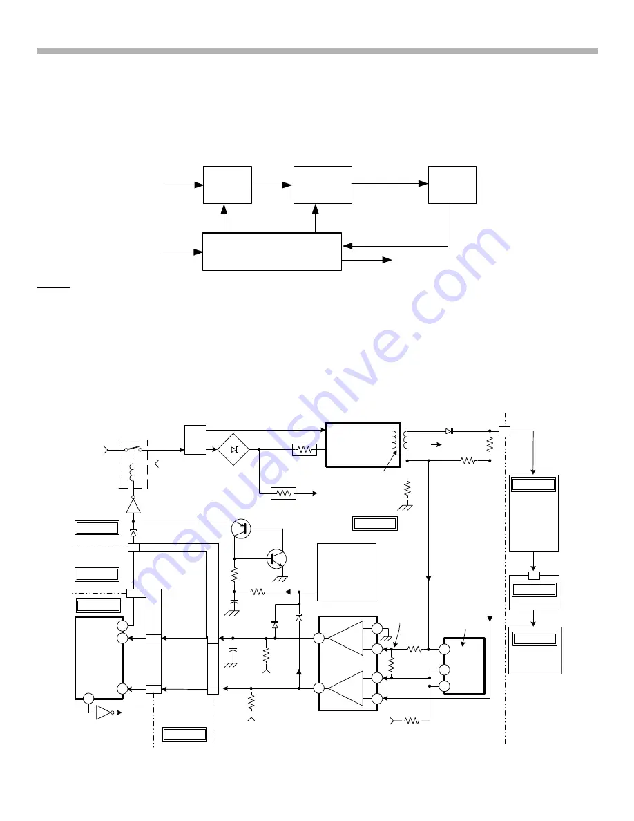
20. RA-5A Chassis Protection Block
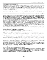
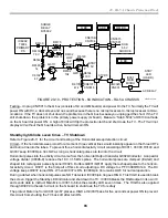
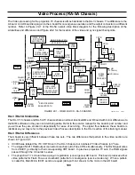
There is also a possibility that a simultaneous loss of communications from the B (IC001) to the A board (IC3006)
and loss of horizontal drive will result in shutdown without a blinking LED, possibly from a broken or contaminated
A board. See Standby light blinks 7X or the overall protection block diagram 33.
Standby light blinks two times – TV Shutdown
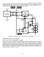
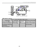
The +135V OCP monitoring circuits are located on the G board, but the indicating circuit is on the B board. This
circuit monitors current drawn by the horizontal regulator that provides power for the horizontal output stage. See
Figure 20-6 below:
AC
Relay
Figure 20-6
AC
Sec P.S.
Main Micro IC001
Pwr
On
AC Relay
Main Relay
OCP
Stby LED Indicator
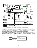
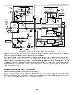
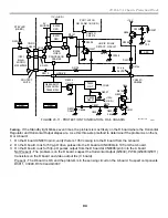
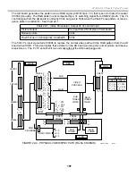
Circuit - Refer to Figure 20-7 for the following circuit description of the 135V load and current sensing circuit.
135V Loads (D, C, A and V boards)
The 135V OCP circuit monitors the current on the +135V line from the Secondary Power Supply to the D, C, A and
V boards. Of all the +135 volt line loads listed, the D board is the most demanding:
•
Horiz Output (Q5030) and PWM (Q5003) stage (D board).
•
The HOT on the D board in turn su200V to the RGB Video Output ICs (C board).
•
33V tuning voltage to analog tuners (A board).
•
Velocity modulation coils (V board).
VEL MOD
COILS
TUNER 33V
IC001
MAIN
MICRO
IC6001,
T6001
SECOND. P.S
AC IN OVP
15VOVP
22VOCP
(NO
INDICATION)
IC6103
uPC
1093J
SW.
SURGE
RELAY
CIRCUIT
4
A26
C25
A25
44
69
45
1
7
3
2
6
5
C6102
100
R6142
STANDBY
5V
3
1
2
A BD.
50
9
G BD.
B BD.
STBY
LED
(H BD.)
D BD.
V BD.
A BD.
Q522
R6102
270k
D6104
T6001
R6118
0.22
R6101
4.7k
CN6106/
CN8013
STANDBY
5V
Q6120
D6001
R6041
R6099
PRI
P.S
G BD.
RY6001
AC RELAY
CN6001
AC IN
ZENER
REF.
CN3016/
CN6101
CN001/
CN3020
Q6105
Q6119
R6119
C6146
10
R6195
D6124
D6123
PROTECT
LATCH
OCP
OVP
R6103
4.7k
R6104
560
V SENSE (ENABLE 2)
IC6102
uPC393C
+
-
+
-
P
N
OCP
OVP
AC
RELAY
STBY 5V
A BD.
9/4/01
28TVP12 1345
10
HV REG/
HV OUT,
H OUT REG/
H OUT,
VIDEO OUT
P.S
2X
3X
2.5V
6
7
+
STBY 5V
R6110
0.27V
FIGURE 20-7 - PROTECTION - 2X, 3X INDICATION - RA-5 CHASSIS
+135V
Summary of Contents for KD-34XBR2 - 34" Hdtv Fd Trinitron Wega
Page 77: ...74 RA 5A Chassis Board Layout ...
Page 108: ...APPENDIX ...

