17
6. Primary Power Supply - HA-3 & RA-5a Chassis
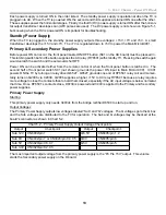
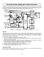
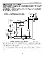
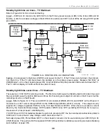
VC1 Powers IC6001
Although the oscillator is running, at this initial frequency of 200kHz there is insufficient current from T6002 to
produce any unregulated 7V or 11V voltage because of the load. On the other hand, there is very little load on
D6011 and D6012, so they output about 15V each at the cathodes (normally about 18Vdc).
The voltage from D6011 is returned to IC6001/pin 8 (VC1) to serve as regulated B+ for the IC.
IC6001 Normal Operation
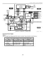
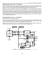
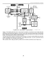
At start up, IC6001 initially uses current limited B+ from pin 18 to power internal drivers. These internal drivers
amplify the oscillator signal and get it out to pins 12 and 16. The power for the internal drivers initially come from
pin 18, but ultimately comes from pins 10 (VC2) and 14 (VB) when the power supply stage begins working. VC2
provides the voltage for the bottom driver (pin 12) while VB provides the voltage for the top driver (pin 16).
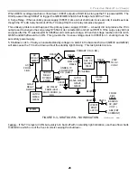
The VC2 voltage comes from the 18Vdc input VC1 (pin 8) that is internally regulated to 10Vdc. The 10Vdc from
VC2 is used to make VB voltage at pin 14. Because there is a square wave at pin 14 (internally from pin 15),
D6004 and C6009 are necessary to keep the DC voltage at pin 10 and the signal at pin 14 separate. D6004
10V from pin 10 into VB pin 14 to power the top internal driver (pin 16).
The reason VB pin 14 measures –28 is because pin 14 starts at the same voltage as pin 15 (-32Vdc), but +10Vdc
is added from D6004. That brings the –32Vdc (+10V =) to -22. Because there is a 50% duty cycle square wave
at pin 14, the voltmeter averages the increase so only half of +10V is measured, producing approximately –32
+5V = -28V at VB pin 14.
The result is a VB voltage that is approxi5V (average) above the reference voltage at IC6001/pin 15.
This voltage supplies the top internal driver that amplifies the oscillator signal that leaves IC6001/pin 16.
Secondary Power Supply Starting
The Pri Pre 15V output of the primary power supply (D6012) is used to enable the secondary power supply. At
start up, the primary oscillator frequency is HIGH so low secondary voltages are output. Pri Pre 15V is only 10Vdc
at start up but rises to a normal 18Vdc. When it rises to 15.6Vdc, the Secondary Power Supply can start.
Therefore, the Secondary Supply cannot start until the Primary Supply is running normally.
Regulator Stage
Concept
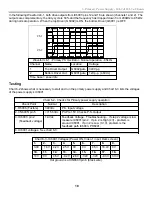
By controlling the frequency of the power supply oscillator, T6002’s secondary output voltage can be regulated.
T6002’s secondary output voltages are dependent upon the match between the output resonate circuit (T6002 =
L, C6019 = C) and the oscillator frequency. When IC6001’s oscillator frequency is the same as the resonate
circuit frequency, there is maximum power transferred in T6002, producing maximum output voltage. By setting
the oscillator frequency above resonance, T6002’s output voltage can be regulated. See Figure 6-2 for the power
output of power transformer T6002.
85kHz = Normal Operation
200kHz @ Start Up
T6002
Output
Frequency
Figure 6-2 –
T6002 Output
Output Voltage Control
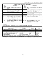
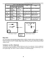
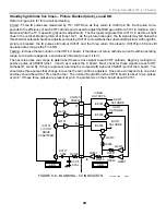
The regulating stage uses error detector IC6003 and optical isolator PH6001 to monitor the Q+6.5V output from
T6002. If the Q+6.5Voutput is LOW, as it is at initial start up (Chart 6-1), the voltage fed back to IC6001/pin 2
goes HIGH, decreasing the oscillator frequency. The decrease in frequency increases the output of the T6002
transformer, until +6.5Vdc is reached.
Chart 6-1 - Regulation Stage – Error Correction Voltages
Q+6.5V Output (D6016)
PH6001/pin 2
IC6001/pin 2
Low
High
High
Summary of Contents for KD-34XBR2 - 34" Hdtv Fd Trinitron Wega
Page 77: ...74 RA 5A Chassis Board Layout ...
Page 108: ...APPENDIX ...


