34
9. High Voltage Power Supply
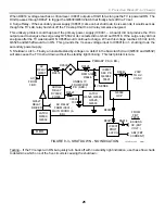
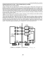
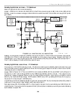
by IC8001/A to output a LOW that keeps Q8003 turned OFF in normal operation. C8005 keeps IC8001/pin 7
LOW at turn ON when there is no HV, to prevent premature HV shutdown. If the HV drops low for a prolonged
period because it is being loaded down or the screen is excessively bright, 33V zener D8025 turns OFF and
inverts all the logic states listed above causing the HV to stop.
Excessive Beam Current (ABL)
Excessive current through the flyback transformer will stop the HV if a momentary bright screen (video game, or
action movie) caused the current demand. This protection circuit monitors the ABL (ground leg of the picture tube
HV feed) line at the FBT using Q8007 and D8005. If the screen brightness rises to a critical level, the low going
ABL voltage is inverted by Q8007, causing a HIGH to pass through D8005 into latch IC8001/pin 7. The latch
outputs and holds the HIGH at pin 7 that turns ON Q8003. Q8003 in turn grounds V Sense IC8002/pin 1 to stop
the HV oscillator. Latch IC8001 resets when the TV is turned OFF.
TV Shutdown
Excessive HV
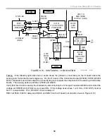
If the HV rises very fast (faster than the IC8001/B HV kill circuit can respond), IC8001/C and D will shut down the
entire TV set. The Standby LED indicator lamp (part of the self-diagnostic circuit) will NOT blink when HV
shutdown occurs.
During a defect when the sample HV from D8014 continues to rise, IC8001/D voltage at pin 9 reaches the +5V
threshold. The HIGH that is output pin 14 passes IC8001/C to produce a HIGH at pin 13. This final HIGH passes
D8027 and is applied directly to the shutdown latch formed by Q6530 and Q6532. When this latch activates,
shutdown occurs so fast that it seems the TV set did not turn on at all. An easy way to prove this HV protection
circuit caused shutdown is to look for a momentary increase in voltage at D8027/cathode during turn ON.
Epoxy sealed RV8001 (at IC8001/pin 9) sets the shutdown threshold. When the HV is correctly set at 31.5kV, the
resultant voltage a test point CN5506/pin 2 is between 4.36–4.66Vdc.
Excessive Current Protection
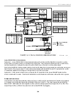
Excessive current drawn along the +200V line into this HV Converter stage will also feed the latch transistors
(Q6530 and Q6532) directly, causing the TV to shut down. When this TV shutdown occurs, there is NO Standby
light blink indication. The +200 line feeds IC8002, the two converter transistors (not shown) and the flyback
transformer. Excessive HV will also cause the TV to shut down by drawing too much current through the flyback.
Excessive Beam Current (ABL)
Excessive current through the flyback transformer will stop the HV and shut down the TV if the HV current drain
is excessive due to a failure. Such a failure can be due to shorted video output ICs, defective CRT or shorted
FBT. When the ABL voltage from the FBT is excessive, Q8008 outputs a HIGH that exceeds 5.1Vdc at latch
IC8001/pin 11. IC8001 outputs a HIGH at pin 13 that passes through D8027 to trip the latch that shuts OFF the
TV.
In summary, shutdown without a Standby light indication indicates a problem is either in this HV stage or in the
shutdown circuit itself.
HV Adjustment
The adjustment procedure for these three controls is straightforward. First, the shutdown controls are preset
(ineffective). Then the RV8002 HV control is set to the shutdown trip point. The two shutdown controls are reset.
Finally, the HV control is set. A HV probe connected to a DVM is required for this precise adjustment procedure.
The procedure is as follows:
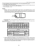
1. Replace RV8001 and RV8002 (they are epoxied).
2. Turn RV8001 both CCW from the top of the D board.
3. Turn the set ON with a black screen (HV unloaded).
Summary of Contents for KD-34XBR2 - 34" Hdtv Fd Trinitron Wega
Page 77: ...74 RA 5A Chassis Board Layout ...
Page 108: ...APPENDIX ...

