


103
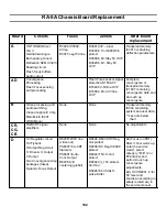
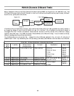
23. RA-5A PJ Chassis Board Replacement
Board
Circuits
Fuses
Zeners
After board
replacement
A
CRT (RGB) Driver
R3024-IC3002-
D3001-33V – tuner
Transplant memory
G
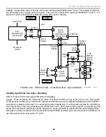
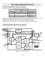
Standby Power Supply
Primary Power Supply
(Sub 6.5V, 11V, 7V.)
Secondary Power
Supply (135V, 22V,
19V, 15V)
Protection latch circuit
F6001-10A-main
R6099-Prim PS
R6041-Sec PS
PS6101-04=135V,
+22V, +15V lines
R6057-Stby PS
R6073, R6081-2-
Pri & Sec PS
sustaining volt.
D6016=AC input OVP
D6121, D6126=15V OVP,
22VOCP
D6133=Sub 6.5V OVP
No adjustments
K
Prologic Decoding
Audio Output
Amplifiers
Tone Control
Pwr On/Off/Ch change
mute
None
S Data protect D2301,
D2303, D2305
S Clk protect D2302,
D2304, D2306
Surround spk protection-
D2602-5
Center Spk protection-
D2619-20
Main spk protection-
D2614-17
Var/Fixed output
protection D2624-31
No adjustments
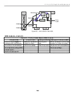
Q Box
(Qi,
QM
Bds)
DRC for line doubling
MID for twin pictures
DTV Tuner and A/V
process
None
D7803-3.9V=Reg for write
PLL IC7805 (QM Bd)
Enter the service
mode and check the
model ID category
items to see if they
agree with the service
manual. ** see note.
U
Audio/Video
Input/output panel
None
None
No adjustments
V
Velocity Modulation
None
None
No adjustments
* Service Mode access using remote buttons: Display, #5, Vol +. Power. See the Convergence Adjustment
Overview chapter for more information on the service mode.
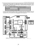
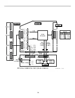
** After replacing the B board or Q box you will find that the plugs to CN8801 and CN8601 are the same. Cables
from Q box to CN004 and CN005 should cross. See Figure 23-1.
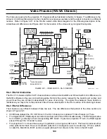
Summary of Contents for KD-34XBR2 - 34" Hdtv Fd Trinitron Wega
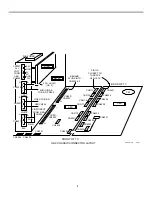
Page 77: ...74 RA 5A Chassis Board Layout ...
Page 108: ...APPENDIX ...