76
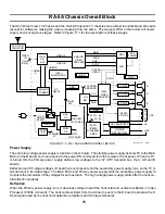
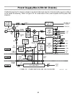
17. RA-5A Chassis Overall Block
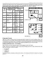
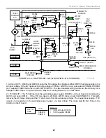
The vertical stage also starts on the A board, but does not deliver its drive signal into the D board without commu-
nications from the Main Micro. The vertical oscillator IC3006 (A board) initially produces only vertical timing
signals (VTIM is not shown) that are applied to Main Micro IC001 (B board). IC001 uses VTIM to output serial
communications data and clock signal to ICs on the I
2
C bus line during the vertical blanking time. This bus line
includes IC3006, which originated the VTIM signal. When data and clock are received by IC3006, this IC can
then output the vertical drive signal from the A board. The V drive feeds deflection IC8003 on the D board. This
completes the vertical and horizontal deflection signal flow.
Video Process
The video processing encompasses the A, B, Q and the three C boards.
B board – Air or cable analog NTSC signal comes into the two tuners mounted on the A board before outputting
composite video to the B board. The tuner video and video 1-6 is applied to A/V Sw IC401 for selection. Two
selections are output. One will be used as the main picture and the other as the sub picture if the Twin View
feature is called for. Both component video outputs are sent to the Q box.
Q Box - The main and sub component video and corresponding sync are sent to the DRC (main picture) and MID
(sub picture) stages in the Q box. Here digital ATSC signals are received from the DTV tuner, processed and
made available to the MID circuit for selection. The MID circuit chooses one (or two if in Twin View mode) and
outputs a high-resolution video signal to IC3006 on the A board. The video signal was also changed so its
frequency matches the 33.75kHz frequency of the horizontal oscillator in IC3006 (A board). Separate sync lines
also go to IC3006 on the A board.
A board – Both sync and component video are sent to the A board. The V & H sync signals are applied to IC3006
for oscillator lock and to supply the convergence circuitry in the AD board. The component video is input IC3006
and converted to RGB. The RGB signal feeds the three CRT’s cathodes.
Convergence
Convergence and Flash focus are independent operations sharing the same microprocessor and memory IC on
the AD board. The AD board plugs into the A board.
Convergence – The purpose of this circuit is to modify the magnetic field in the main yoke of all three CRTs so
their colored pictures become merged as one on the TV screen. There are two outputs from this board. One
output is the main convergence signal consisting of RGB vertical and horizontal signals that feed the two conver-
gence amplifiers on the D board. These convergence amplifiers output a final convergence signal that is applied
to the convergence yoke within the main yoke. The second output is a pattern signal consisting of an RGB signal
that is sent to Video Processor IC3006 for OSD. The pattern signal can be a crosshatch pattern for convergence
or positioning boxes flash focus adjustment. Convergence settings are stored in a NVM IC within the AD board
and shared with flash focus position information. This information should not be confused with Geometry settings
for all three CRTs that are stored in a NVM (memory) on the A board.
Flash Focus – This user operation on the AD board automatically adjusts centering and now also adjusts size and
linearity (new). The flash focus circuit produces a TV screen pattern using RGB output from the AD board into the
A board’s IC3006. The OSD positioning boxes are monitored by six sensors mounted at the screen edges to
provide feedback to the AD board’s flash focus circuitry for adjustment. The picture is converged and the center-
ing, size and linearity data is modified in the memory on the AD board.
Summary of Contents for KD-34XBR2 - 34" Hdtv Fd Trinitron Wega
Page 77: ...74 RA 5A Chassis Board Layout ...
Page 108: ...APPENDIX ...


