80
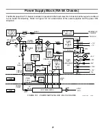
18. RA-5A Chassis - Power Supply Block
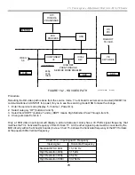
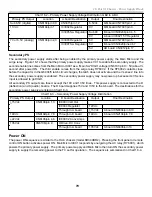
Chart 18-4 - Power On Sequence
Step
Action
Verification
1. Press Power On
button
Main Micro receives the command
2. AC Relay activates
Main Micro (B bd) activates AC relay RY6001 (G bd)
G board CN6101/pin 4 =
5Vdc
3. Primary PS powered
B+ applied to primary PS to start & run
G board CN6106/pin 8 or 9
= 6.5Vdc
4. Surge Relay
activates
Primary PS output Sub 6.5 energizes surge relay
RY6002
G board - Feel for click in
rear relay RY6002. RY6001
is nearest the line cord.
5. Secondary PS is
enabled 1.
VC1 voltage (15V) from Primary PS D6049/C enables
the secondary PS.
G board - D6049/Cathode =
15.6V minimum
6. Secondary PS is
enabled 2
Main Micro IC001 turns on Secondary PS.
G board CN6101/pin 9 =
5Vdc
7. Secondary PS
powered
Secondary PS starts and runs powering TV
G board CN6106/pin 9 =
135Vdc
8. VTIM (vertical
timing) pulses input
Main Micro IC001
Video Processor (Jungle) IC3006 on A board gets
9Vdc operating voltage from Primary PS and outputs
VTIM pulses to IC001 and IK test drive to CRT (in V
blanking area of the CRT above the screen)
A board CN3014/pin 1 =
11V (regulated to 9Vdc on
the A board)
9. Picture appears
Main Micro IC001 instructs Video Process IC3006 to
output vertical drive and unblanks picture if IK signal
is OK.
A board Serial data port
CN3009/pins 10 (data), &
pin 11 (clk).
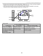
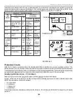
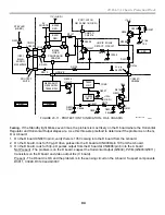
D6049
AC input
G board
RY6002
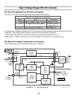
FIGURE 18-3
Summary of Contents for KD-34XBR2 - 34" Hdtv Fd Trinitron Wega
Page 77: ...74 RA 5A Chassis Board Layout ...
Page 108: ...APPENDIX ...

