16
6. Primary Power Supply - HA-3 & RA-5a Chassis
Primary Power Supply (HA-3 & RA-5A Chassis)
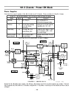
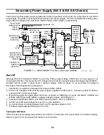
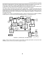
The Primary and Secondary power supplies are similar in operation. They differ in schematic nomenclature
(component numbers) and output voltages. The HA-3 simplified secondary power supply is shown in Figure 6-1
for this description.
The primary power supply on the HA-3 chassis A board consists of three parts:
1. Oscillator 2. Output stage 3. Regulator Stage
The oscillator starts up to produce an initial signal for the output stage. The output stage develops voltage to
continue running the oscillator stage, supply the regulating stage, and provide normal output for the TV. One of
the normal TV outputs is used to start the secondary power supply.
PH6001
OPTICAL
ISOLATOR
R6023
R6020
N
CH
N
CH
IC6001
DRIVER
MCZ3001D
16
12
9
15
18
2
6
8
10
14
1
2
C6009
1
IC6003
ERROR DET.
uPC1093C
3
1
AC RECT.+
FROM
IC6501/1
(D BD.)
R6002
0.47 OHMS
R6010
R6001
R6003
R6004
R6006
C6007
VC1 VC2
VB
F/B
OCP
R6009
+
+
T6002
Q6002
Q6001
TIMER
R6018
R6019
R6041
R6045
D6016
C6014
D6011
D6012
D6018
D6014
PRI
PRE 15V (D
BD.)
UNREG.
7V SOURCE
UNREG. 11V
SOURCE
V
SENSE
340VDC
3V
1.86V
D6004
18V
A BD.
R6040
Q +6.5V
SOURCE
8/30/01
23TVP12 1341
-32V
4.5V
10V
-28V
OV
-32V
V
D
V
G(H)
V
S
V
G(L)
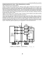
FIGURE 6-1 - PRIMARY POWER SUPPLY - HA-3 CHASSIS
Oscillator Start Up
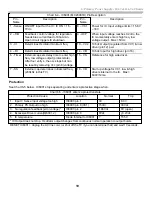
The oscillator within IC6001 starts if the V Sense input voltage at pin 1 is above 1.3Vdc, but less than 8Vdc.
Sample voltage from pin 18 is then used to run the internal oscillator. The initial frequency is approximately
200kHz. The low amplitude initial oscillator signal is output IC6001/pins 12 and 16 into the driver/output stage.
Driver / Output stage
The oscillator voltage output at pins 12 and 16 use drivers Q6001 and Q6002 to develop T6002 secondary
voltages. IC6001’s oscillator will shut down if the driver transistor’s current is excessive. To prevent premature
shutdown, the timer capacitor C6007 delays the shutdown.
Summary of Contents for KD-34XBR2 - 34" Hdtv Fd Trinitron Wega
Page 77: ...74 RA 5A Chassis Board Layout ...
Page 108: ...APPENDIX ...

