82
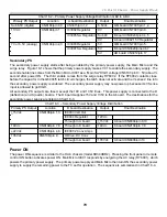
19. Projection TV RA-5A Chassis Power Supply Board Tests
B. Powering Up the G board removed from the TV Chassis
When the board is removed from the chassis, the micro that turns ON the two power supplies must be simulated.
Two jumper wires must be installed - the first to bypass the AC relay and the second to enable the secondary
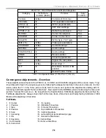
power supply. If good, the G board will then power up and produce all the voltages listed in Chart 19-1.
Required Materials: Soldering iron, short wires, AC cord, DVM, 1k ohm resistor.
Procedure:
1. Remove the G board. Be careful of the voltages across the larger capacitors (350Vdc max).
2. Plug AC into CN6001 (by the glass fuse).
3. Verify “Standby 5Vdc” from the G board at CN6101/pin 1.
4. Unplug the AC and place a jumper wire across CN6101/pins 1, 4 and 9.
5. Plug the board into AC. Both Primary and Secondary power supplies should work and you should be able to
measure the voltages at connector CN6104 (chart 1). If the AC relay does not remain ON, the protection
circuit has sensed a problem on the G board such as excessive output voltage or a defective latch.
6. To check the other voltages, the secondary power supply must be turned ON. Place a jumper wire across the
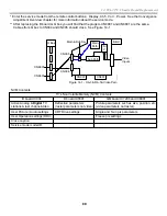
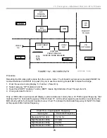
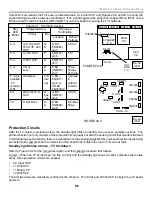
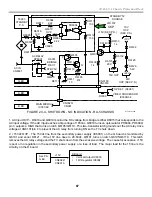
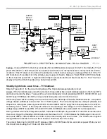
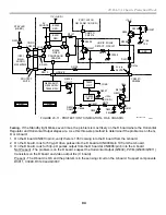
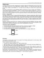
B-E of surface package Q6003 (near heat sinked Q6007). See Figure 19-1 to locate Q6003.
B
E
C
7. Plug the board into AC. You should be able to measure the remaining output voltages (Chart 19-1).
8. Caution
- Before plugging the connectors back into the G board, you must discharge the unloaded voltages
to avoid damaging parts on the A and D boards. Hold a 1k ohm resistor to the following * unloaded terminals
and ground. Connect the resistor at each terminal for 10 seconds. CN6104/pin 1 (11V), CN6104/pin 2 (7V),
CN6106/pin 1 (-15V). The remaining voltages will dissipate within 10 seconds.
C. Powering up the G board power supplies after parts replacements
To avoid damaging the new parts installed to the primary or secondary power supplies, it is important to gradually
apply power to the parts so you can detect a problem before the parts are damaged. In the following steps you will
start the oscillator IC using an external power supply, then gradually bring up the input AC voltage with a variable
AC transformer (Variac) while monitoring the AC input current and output voltage. The output voltage will be kept
at a minimum by disabling the regulator circuit.
Needed Materials: Soldering iron, short wires, AC cord, DVM, 1k ohm resistor, 68k ohm resistor, diode, 16V DC
power supply, AC Variac, scope.
Procedure:
Running just the Primary Power Supply
1. Place a jumper wire across the contacts of AC relay RY6001. See Figure 19-1 for the location of parts.
2. Short PH6005/pins 3-4 to disable the regulating circuit. This prevents the oscillator from pulsing on and off at
low AC input voltages before regulation takes over.
3. Connect a 68k-ohm resistor between IC6002/pins 1 and 7.
4. Connect the band end of a rectifier/diode to IC6002/pin 7. The diode protects your power supply by prevent-
ing the TV’s DC from entering your supply.
5. Connect the anode (unbanded) end of the diode to an external variable DC power supply.
6. The external power supply’s negative lead goes to HOT ground at large cap C6010 neg. terminal or D6001’s
heat sink nearby.
7. Bring the external power supply to 12Vdc (23ma).
8. Connect one end of an AC line cord to CN6001 and the other to the AC Transformer (Variac) set to 0Vac.
Summary of Contents for KD-34XBR2 - 34" Hdtv Fd Trinitron Wega
Page 77: ...74 RA 5A Chassis Board Layout ...
Page 108: ...APPENDIX ...

