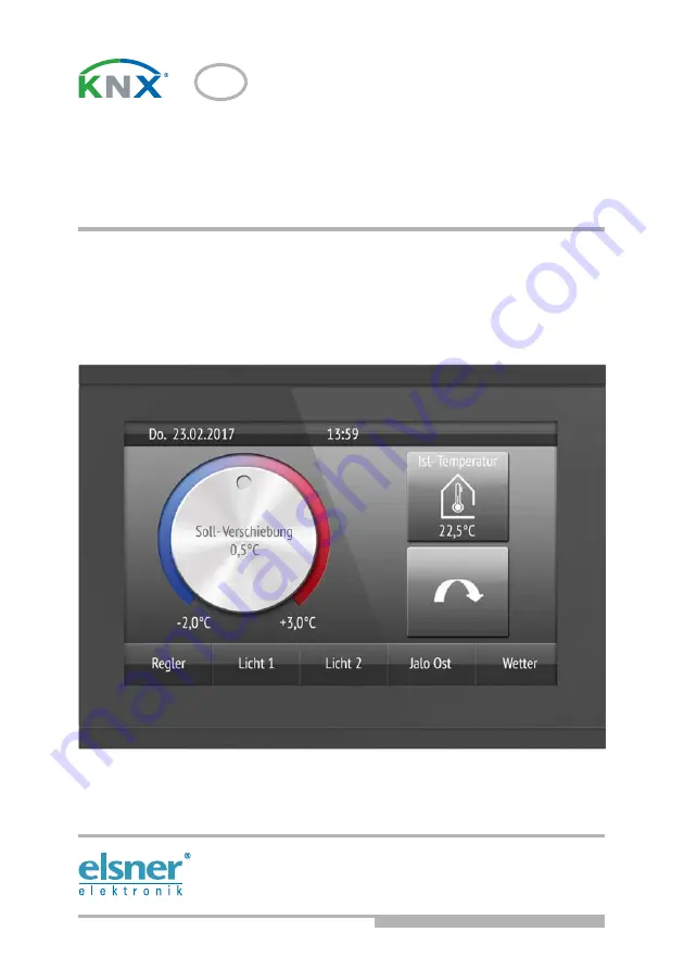
background image

EN

Corlo Touch KNX 5in
Corlo Touch KNX 5in WL

Display and Touch Switch 

Technical support: +49 (0) 70 33 / 30 945-250


Elsner Elektronik GmbH 

Control and Automation Engineering

Sohlengrund 16
75395 Ostelsheim

Phone +49 (0) 70 33 / 30 945-0

[email protected]

Germany

Fax

+49 (0) 70 33 / 30 945-20 www.elsner-elektronik.de

Technical specifications and installation instructions

Item numbers 70475 (Corlo Touch KNX 5in WL), 70481 (Corlo Touch KNX 5in)

Summary of Contents for Corlo Touch KNX 5in

Page 1: ...r Elektronik GmbH Control and Automation Engineering Sohlengrund 16 75395 Ostelsheim Phone 49 0 70 33 30 945 0 info elsner elektronik de Germany Fax 49 0 70 33 30 945 20 www elsner elektronik de Technical specifications and installation instructions Item numbers 70475 Corlo Touch KNX 5in WL 70481 Corlo Touch KNX 5in ...

Page 2: ...the Corlo Touch KNX 5in WL model you can display predefined web pages using the WLAN connection You enter URL addresses in the ETS Icons for display can be exchanged symbol library in the device own pictures from by micro SD card Ambient lighting with individually variable colors RGB Integrated proximity sensor Enables proximity switching and fast activation of the display from standby mode Integr...

Page 3: ...ns Housing overall approx 133 97 35 W H D mm Mounting depth approx 20 mm Weight display unit Corlo Touch KNX 5in approx 200 g Weight display unit Corlo Touch KNX 5in WL approx 210 g Ambient temperature Operation 0 50 C storage 10 50 C Ambient humidity max 95 RH avoid condensation Operating voltage 24 V DC 10 Power consumption Corlo Touch KNX 5in approx 2 7 W maximum when ambient lighting 100 white...

Page 4: ...shooting should only be performed by an electrician CAUTION Live voltage There are unprotected live components inside the device National legal regulations are to be followed Ensure that all lines to be assembled are free of voltage and take precautions against accidental switching on Do not use the device if it is damaged Take the device or system out of service and secure it against unintentiona...

Page 5: ... occur after publication of these operating instructions 2 2 Installation 2 2 1 Assembly site and assembly preparations The device must only be installed and operated in dry indoor spaces Avoid condensation ATTENTION The WLAN range for the Corlo Touch KNX 5in WL model can be reduced as a result of the position where it is installed Consider this when planning the location Avoid direct light sunlig...

Page 6: ... point upwards Two screws right left or top bottom are enough TOP Fig 3 If the screw domes of the box used are not cov ered with the mounting unit s longitudinal holes the mounting unit can alternatively be bolted via the other holes e g for other installation sys tems Fig 4 Example Boxes from Swiss systems Fig 5 The display unit can now be put in place The arrow placed on the back TOP must point ...

Page 7: ...echnical changes and errors reserved Fig 6 Fix the display unit from below with the supplied screw A A Fig 7 To remove the display unit from the mounting unit loosen the screw A Press against the lo wer notches B to release the connection The display unit can be removed A B B ...

Page 8: ...puts can be extendet to up to 10 m All GND connections of the inputs are bridged internally black cable Fig 8 1 Monting unit 2 Terminal auxiliary supply 24 V DC 10 terminal configuration inde pendent from polarity 3 Display unit 4 Notches for snaplock 5 Aperture für Screw fixing 6 KNX terminal bus 7 Programming button for addressing the device at the bus recessed 8 Analog digital inputs socket 9 V...

Page 9: ...ng the device The programming mode for addressing at the bus is activated via the programming button at the back of the housing or via the display Settings System Service KNX 4 Setting up the WLAN connection Only for the Corlo Touch KNX 5in WL model with an interface for wireless network connection 4 1 WLAN settings in the ETS The WLAN connection must be set up in the ETS Consult the WLAN setting ...

Page 10: ...ngth IP address DNS address and GW address are displayed Settings System Service WLAN Status 3 11 7 WLAN Status 5 Maintenance and care Fingerprints on the glass area and frame are best removed with a cloth moistened with water or a microfiber cloth Do not use an abrasive cleaning agent or aggressive cleansing agents For cleaning of the screen the cleaning mode can be used that is activeted via the...

Page 11: ... the SD card carry out a reset in the menu after inserting it Settings System Reset This is not necessary if the card was inserted before booting the system The card must remain in the device Store images in the given size in a corresponding folder on the top level of the SD card Stationary images must have a 4 digit numerical sequence so that they can be called up in the ETS and in the menu 0001 ...

Page 12: ...ystem The card must remain in the device Store images in the given size in a corresponding folder on the top level of the SD card Icons must have a 4 digit numerical sequence so that they can be called up in the ETS and in the menu 0001 9999 Image type Resolution File format Folder name Symbol small icon 96 96 pixels png icons Icons for rotary control 316 320 pixels png icons ...

Reviews: