


G-8
Setting SEL
OGIC
Control Equations
Date Code 20011205
SEL-311B Instruction Manual
instead of with Relay Word bits. If a SEL
OGIC
control equation setting is set directly to 1, it is
always “asserted/on/enabled.” If a SEL
OGIC
control equation setting is set equal to 0, it is
always “deasserted/off/disabled.”
Note:
SEL
OGIC
control equation torque control settings (e.g., 67P1TC, 51P1TC) cannot be set
directly to logical 0.
Under the
SHO Command (Show/View Settings)
in
Section 10: Serial Port Communications
and Commands
, note that a number of the factory SEL
OGIC
control equation settings are set
directly to 1 or 0.
The individual SEL
OGIC
control equation settings explanations (referenced in Settings Sheets 11
through 15 at the end of
Section 9: Setting the Relay
) discuss whether it makes logical sense to
set the given SEL
OGIC
control equation setting to 0 or 1 for certain criteria.
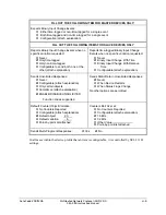
Set SEL
OGIC
Control Equations Directly to 1 or 0—Example
Of special concern are the SEL
OGIC
control equation torque control settings 67P1TC through
51QTC for the overcurrent elements. In the factory settings included in a standard shipment of a
SEL-311B Relay, these are all set directly to logical 1. See these factory settings in
SHO
Command (Show/View Settings)
in
Section 10: Serial Port Communications and Commands
.
If one of these torque control settings is set directly to logical 1
e.g., 67QTC = 1
(set directly to logical 1)
then the corresponding overcurrent element is subject only to the directional control. See
Figure 3.19 in
Section 3: Distance, Overcurrent, Voltage, and Synchronism Check Elements
for negative-sequence overcurrent element 67QTC logic.
SEL
OGIC
Control Equation Limitations
Any single SEL
OGIC
control equation setting is limited to
15
Relay Word bits that can be
combined together with the SEL
OGIC
control equation operators listed in Table G.1. If this limit
must be exceeded, use a SEL
OGIC
control equation variable (SEL
OGIC
control equation settings
SV1 through SV16) as an intermediate setting step.
For example, assume that the trip equation (SEL
OGIC
control equation trip setting TR) needs
more than 15 Relay Word bits in its equation setting. Instead of placing all Relay Word bits into
TR, program some of them into the SEL
OGIC
control equation setting SV1. Next use the
resultant SEL
OGIC
control equation variable output (Relay Word bit SV1) in the SEL
OGIC
control equation trip setting TR.
Note that the SEL
OGIC
control equation variables (SEL
OGIC
control equation settings SV1
through SV16) are processed after the trip equation (SEL
OGIC
control equation trip setting TR).
Thus, any tripping via Relay Word bits SV1 through SV16 can be delayed as much as 1/4 cycle.
For most applications, this is probably of no consequence.
The SEL
OGIC
control equation settings as a whole are limited to no more than 447 elements and
49 rising-edge or falling-edge operators.
Summary of Contents for SEL-311B
Page 6: ......
Page 8: ......
Page 10: ......
Page 24: ......
Page 26: ......
Page 122: ......
Page 124: ......
Page 138: ......
Page 168: ......
Page 172: ......
Page 254: ......
Page 282: ......
Page 306: ......
Page 348: ......
Page 364: ......
Page 366: ......
Page 448: ......
Page 460: ......
Page 466: ......
Page 476: ......
Page 482: ......
Page 494: ......
Page 500: ......
Page 522: ......
Page 526: ......
Page 528: ......
Page 534: ......
Page 536: ......
Page 550: ......
Page 570: ......
Page 586: ......
Page 600: ......