


Date Code 20011205
Testing and Troubleshooting
13-7
SEL-311B Instruction Manual
magnitude of voltage you should apply to the relay logic inputs. Approximately four
milliamps of current flow when rated voltage is applied to a relay logic input.
The V/phase specification indicates the nominal ac voltage that the relay is designed
to measure. This voltage is specified from line to neutral and assumes a standard 4-
wire wye ac voltage connection. This relay is configured to accept 67 volts ac, line
to neutral. The relay measures other ac voltage magnitudes accurately, as defined in
Section 1: Introduction and Specifications
.
The Amps specification indicates the nominal ac current (1 A or 5 A) that the relay
is designed to measure. The relay measures other ac current magnitudes accurately,
as defined in
Section 1: Introduction and Specifications
.
Step 3.
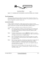
Purpose: Connect power supply voltage to the relay.
Method: Connect a frame ground to terminal marked GND on the rear panel and
connect a voltage source to the terminals and -. Polarity is unimportant.
Relays equipped with 125 or 250 V power supplies may be powered from a 115 Vac
wall receptacle for testing. In the final installation, we recommend that the relay
receive control power from the station dc battery. This helps prevent loss of relay
event reports stored in volatile memory if station ac service is lost.
Step 4.
Purpose: Apply power supply voltage to the relay and access the relay via the
optional LCD front panel.
Method: Turn on the voltage source connected to the relay power supply inputs If
you are using a battery simulator as the relay power supply voltage source, be sure
the simulator voltage level is stabilized.
The relay front panel Enable target (EN) should illuminate.
EN
should appear in the
relay LCD screen.
The relay output labeled ALARM is typically configured as a normally closed (form
“b”) contact and closes to indicate loss of dc power to the relay, failure of a relay
self-test, and several other functions. With power applied to the relay and the relay
turned on, the ALARM contacts open.
If the Enable LED does not illuminate or
EN
does not appear on the relay LCD
screen, turn off the power and refer to Relay Troubleshooting later in this section.
Step 5.
Purpose: Perform a front panel LED test and check LCD screen contrast.
Method: Press the
TARGET RESET
button to perform an LED lamp test. During
the lamp test, the relay illuminates all 16 front panel LEDs for about one second.
The relay also turns on the LCD back lighting. If the LCD contrast is poor, refer to
the Troubleshooting Procedure in this section for steps to adjust it.
Step 6.
Purpose: Verify the relay self-test status.
Method: Press the front panel
STATUS
button. The message
STATUS: OK
should appear on the relay LCD screen. Use the Up and Down arrow buttons to
view the results of specific relay self-tests. Press the front panel
EXIT
button to exit
the STATUS display.
Summary of Contents for SEL-311B
Page 6: ......
Page 8: ......
Page 10: ......
Page 24: ......
Page 26: ......
Page 122: ......
Page 124: ......
Page 138: ......
Page 168: ......
Page 172: ......
Page 254: ......
Page 282: ......
Page 306: ......
Page 348: ......
Page 364: ......
Page 366: ......
Page 448: ......
Page 460: ......
Page 466: ......
Page 476: ......
Page 482: ......
Page 494: ......
Page 500: ......
Page 522: ......
Page 526: ......
Page 528: ......
Page 534: ......
Page 536: ......
Page 550: ......
Page 570: ......
Page 586: ......
Page 600: ......