


4-10
Loss-of-Potential, CCVT Transient Detection,
Date Code 20011205
Load-Encroachment, and Directional Element Logic
SEL-311B Instruction Manual
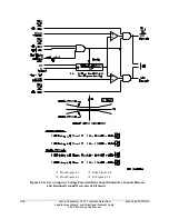
Note in Figure 4.5 that setting ORDER enables the directional elements. Setting ORDER can be
set with any combination of Q, V, and I. They have the following correspondence to the
directional elements:
Q Negative-sequence voltage-polarized directional element
V Zero-sequence voltage-polarized directional element
I Channel IP current-polarized directional element
The order in which these directional elements are listed in setting ORDER determines the priority
in which they operate to provide Best Choice Ground Directional
™
logic control. See discussion
on setting ORDER in the following subsection
Directional Control Settings
.
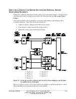
Directional Element Enables
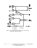
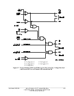
Refer to Figure 4.5, Figure 4.6, and Figure 4.7.
The directional element enables, Relay Word bits 32QGE, 32VE, and 32IE have the following
correspondence to the directional elements:
32QGE
Negative-sequence voltage-polarized directional element
32VE
Zero-sequence voltage-polarized directional element
32IE
Channel IP current-polarized directional element
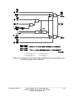
Note that Figure 4.6 has extra directional element enable 32QE, which is used in the logic that
controls phase distance elements (see Figure 4.14).
The settings involved with 32QGE, 32VE, and 32IE in Figure 4.6 and Figure 4.7 (e.g., settings
a2, k2, a0) are explained in the following subsection
Directional Control Settings
.
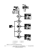
Best Choice Ground Directional Logic
Refer to Figure 4.5 and Figure 4.8.
Relay Word bits 32QGE, 32VE, and 32IE and setting ORDER are used in the Best Choice
Ground Directional logic in Figure 4.8. The Best Choice Ground Directional logic determines the
order in which the directional element should be enabled to operate. The ground distance and
residual ground overcurrent elements set for directional control are then controlled by this
directional element.
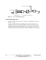
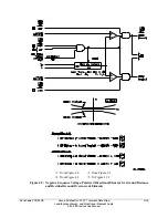
Directional Elements
Refer to Figure 4.5, Figure 4.9, Figure 4.10, and Figure 4.11.
The enable output of Best Choice Ground Directional logic in Figure 4.8 determines which
directional element will run.
Additionally, note that if enable setting ELOP = Y or Y1 and a loss-of-potential condition occurs
(Relay Word bit ILOP asserts), the negative-sequence voltage-polarized and zero-sequence
voltage-polarized directional elements are disabled (see Figure 4.9 and Figure 4.10).
Summary of Contents for SEL-311B
Page 6: ......
Page 8: ......
Page 10: ......
Page 24: ......
Page 26: ......
Page 122: ......
Page 124: ......
Page 138: ......
Page 168: ......
Page 172: ......
Page 254: ......
Page 282: ......
Page 306: ......
Page 348: ......
Page 364: ......
Page 366: ......
Page 448: ......
Page 460: ......
Page 466: ......
Page 476: ......
Page 482: ......
Page 494: ......
Page 500: ......
Page 522: ......
Page 526: ......
Page 528: ......
Page 534: ......
Page 536: ......
Page 550: ......
Page 570: ......
Page 586: ......
Page 600: ......