


Date Code 20011205
Inputs, Outputs, Timers, and Other Control Logic
7-3
SEL-311B Instruction Manual
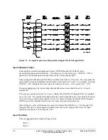
Optoisolated inputs IN101 through IN106 receive their function by how their corresponding
Relay Word bits IN101 through IN106 are used in SEL
OGIC
control equations.
Settings Example 1
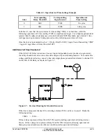
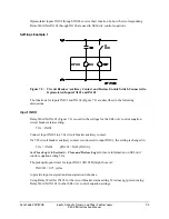
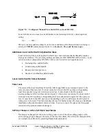
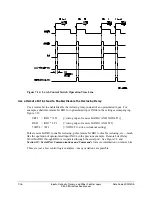
Figure 7.2: Circuit Breaker Auxiliary Contact and Reclose Enable Switch Connected to
Optoisolated Inputs IN101 and IN102
The functions for inputs IN101 and IN102 (Figure 7.2) are described in the following
discussions.
Input IN101
Relay Word bit IN101 (Figure 7.2) is used in the settings for the SEL
OGIC
control equation
circuit breaker status setting:
52A = IN101
Connect input IN101 to a 52a circuit breaker auxiliary contact.
If a 52b circuit breaker auxiliary contact is connected to input IN101, the setting is changed to:
52A = !IN101
[!IN101 = NOT(IN101)]
See
Close Logic
in
Section 6: Close and Reclose Logic
for more information on SEL
OGIC
control equation setting 52A.
The pickup/dropout timer for input IN101 (IN101D) might be set at:
IN101D = 0.75 cycles
to provide input energization/deenergization debounce.
Using Relay Word bit IN101 for the circuit breaker status setting 52A does not prevent using
Relay Word bit IN101 in other SEL
OGIC
control equation settings.
Summary of Contents for SEL-311B
Page 6: ......
Page 8: ......
Page 10: ......
Page 24: ......
Page 26: ......
Page 122: ......
Page 124: ......
Page 138: ......
Page 168: ......
Page 172: ......
Page 254: ......
Page 282: ......
Page 306: ......
Page 348: ......
Page 364: ......
Page 366: ......
Page 448: ......
Page 460: ......
Page 466: ......
Page 476: ......
Page 482: ......
Page 494: ......
Page 500: ......
Page 522: ......
Page 526: ......
Page 528: ......
Page 534: ......
Page 536: ......
Page 550: ......
Page 570: ......
Page 586: ......
Page 600: ......


