


72
02-06
Vector control slip gain
Factory setting
100%
Setting range 50%
~
200%
For speed sensorless vector control, this parameter is used to adjust the speed stability accuracy of the motor:
when the motor is loaded with a low speed, increase this parameter, and vice versa.
02-07
Digital setting of torque upper limit in speed control mode
Factory setting
150.0%
Setting range 0.0%
~
200.0%
In speed control mode, the maximum value of the inverter's output torque is selected by the upper torque source
02-10. When the analog, PULSE pulse, and communication settings are selected, the corresponding set 100%
corresponds to 02-07, 100% is the rated torque of the inverter.
02-08
Speed loop filter time constant
Factory setting
0.015s
Setting range 0.000s
~
0.100s
In vector control mode, this parameter is used to filter the speed loop torque command. This parameter generally
does not need to be adjusted. When the speed fluctuation is large, the filtering time can be increased
appropriately; if the motor oscillates, the parameter should be appropriately reduced. The speed loop filter time
constant is small, the output torque of the inverter may fluctuate greatly, but the speed response is fast.
02-09
Vector control over excitation gain
Factory setting
64
Setting range 0
~
200
During deceleration of the inverter, overexcitation control can suppress the rise of bus voltage and avoid
overvoltage faults. The greater the overexcitation gain, the stronger the suppression effect.
However, if the gain is too large, it is easy to cause the output current to increase, which needs to be set
appropriately. For the occasions with small inertia and braking resistance, it is recommended to set the gain to 0.
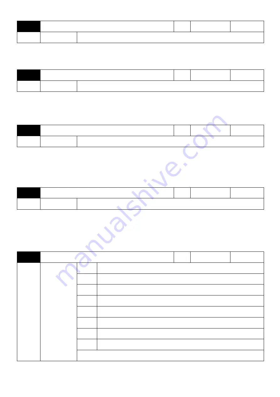
02-10
Torque upper limit source in speed control mode
Factory setting
0
Setting range
0
Parameter setting
1
AVI1
2
AVI2/ACI
3
reserved
4
Pulse setting
5
Communication setting
6
MIN(AVI1,AVI2/ACI)
7
MAX(AVI1,AVI2/ACI)
The full scale of the 1-7 option corresponds to 02-07
In speed control mode, this parameter is used to select the torque upper limit source of the inverter.
Summary of Contents for S3100A Series
Page 1: ...S3100Aseries inverter General Open loop Vector Control IM User manual User Manual ...
Page 24: ...20 Size 5 Unit mm S3100A 4T45G 55P 4T110G Size 6 Unit mm S3100A 4T110G 132P 4T160G 185P ...
Page 25: ...21 Size 7 Unit mm S3100A 4T185G 200P 4T220G Size 8 Unit mm S3100A 4T220G 250P 4T315G ...
Page 26: ...22 Size 9 Unit mm S3100A 4T315G 355P 4T400G 450P Size 10 Unit mm S3100A 4T450G 500P 4T500G ...


