background image


112

AUX send/MATRIX send


AUX send/MATRIX send


fig.PopAuxSends.eps


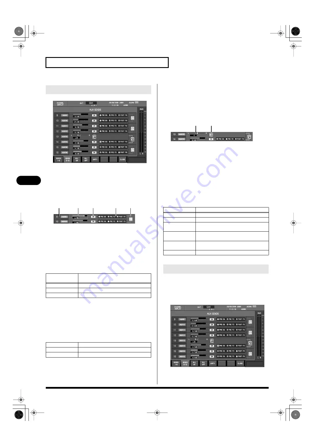
You can use the tabs in the AUX SENDS popup to switch between 
two display pages: sends to AUX1–AUX8 (SENDS 1-8) or sends to 
AUX9–AUX16 (SENDS 9-16).


AUX sends 1–8, AUX sends 9–16


These adjust the sends from the CH to AUX. The AUX send 
area is structured as follows.


fig.PopAuxSendFieldGuide.eps


1.


AUX number and name


This indicates the AUX channel number and name.


2.


Send level bar


This adjusts the send level to AUX in a range of -Inf dB–+10.0 
dB.

The color of the send level bar indicates the send point or the 
status of the send switch, as follows.


3.


ON button


This turns the send switch on/off. The send switch turns the 
signal from the channel to AUX on/off.


4.


send point select buttons


These select the point from which the CH signal is sent to AUX, 
from the following choices.


5.


AUX LINK switch


This turns linking of adjacent odd-numbered/even-numbered 
AUX channels on/off. If this is on, the adjacent AUX channels 
will be linked.

If AUX is stereo-linked, the following parameters will be shown 
for the odd-numbered AUX send.


fig.PopAuxSendField2Guide.eps


1.


AUX pan slider


This adjusts the left/right panning of the signal sent to the 
stereo-linked AUX channels in a range of L63–R63.


2.


PAN LINK button (input channels only)


This turns the PAN LINK switch on/off. If PAN LINK is on, the 
pan from the channel to MAIN L/R will be linked with the pan 
from the channel to the stereo-linked AUX channels.

In the AUX SENDS popup, the function buttons perform the 
following operations.


1.


In the fader module section, press a [SEL] button to select 
the desired channel.


2.


In the AUX SENDS area of the CHANNEL EDIT section, 
press [DISP].


fig.PopAuxSends.eps


The AUX SENDS popup will appear.


AUX SENDS popup


Color of the 
send level bar

Status


Blue

PRE EQ or PRE FADER send point

Green

POST FADER send point

Gray

Send switch is off

PRE EQ

Send from the pre-EQ point.

PRE FD

Send from the pre-fader point.

POST FD

Send from the post-fader point

1

2

3

4

5


Button

Function


[F1 (SENDS 1-8)]

Displays the sends to AUX1–AUX8.

[F2 (SENDS 9-16)]

Displays the sends to AUX9–AUX16.

[F3 (ALL ON)

Turns on all send switches for each send 
field.

[F4 (ALL OFF)

Turns off all send switches for each send 
field.

[F5 (UNITY)

Sets the send level to 0.0 dB for the send field 
at the cursor location.

[F8 (CLOSE)] 

Closes the popup.


Accessing the AUX SENDS popup

1

2

M-400_v15_e.book 112 ページ 2008年6月20日 金曜日 午後4時5分

Summary of Contents for M-400

Page 1: ...aseo García Faria 33 35 08005 Barcelona SPAIN TEL 93 493 91 00 CROATIA ART CENTAR Degenova 3 HR 10000 Zagreb TEL 1 466 8493 CZECH REP CZECH REPUBLIC DISTRIBUTOR s r o Voctárova 247 16 CZ 180 00 PRAHA 8 CZECH REP TEL 2 830 20270 DENMARK Roland Scandinavia A S Nordhavnsvej 7 Postbox 880 DK 2100 Copenhagen DENMARK TEL 3916 6200 EUROPE OCEANIA Roland Corporation Australia Pty Ltd 38 Campbell Avenue De...

Page 2: ...if battery is incorrectly replaced Replace only with same or equivalent type WARNING To reduce the risk of fire or electric shock do not expose this apparatus to rain or moisture For the USA DECLARATION OF CONFORMITY Compliance Information Statement Model Name Type of Equipment Responsible Party Address Telephone M 400 Digital Mixer Roland Systems Group U S 425 Sequoia Drive Suite 114 Bellingham W...

Page 3: ...er alone or in combination with an amplifier and headphones or speakers may be capable of producing sound levels that could cause permanent hearing loss Do not operate for a long period of time at a high volume level or at a level that is uncomfortable If you experience any hearing loss or ringing in the ears you should immediately stop using the unit and consult an audiologist 011 Do not allow an...

Page 4: ...y to excessive heat such as sunshine fire or the like 101a The unit should be located so that its location or position does not interfere with its proper venti lation 102b Always grasp only the plug on the power supply cord when plugging into or unplugging from an outlet or this unit 103a At regular intervals you should unplug the power plug and clean it by using a dry cloth to wipe all dust and o...

Page 5: ...mage if you mistakenly supply phantom power to dynamic microphones audio playback devices or other devices that don t require such power Be sure to check the specifica tions of any microphone you intend to use by referring to the manual that came with it This instrument s phantom power 48V DC 14mA Max M 400_v15_e book 5 ページ 2008年6月20日 金曜日 午後4時5分 ...

Page 6: ... as cell phones are operated in the vicinity of this unit Such noise could occur when receiving or initi ating a call or while conversing Should you experience such problems you should relocate such wireless devices so they are at a greater distance from this unit or switch them off 354a Do not expose the unit to direct sunlight place it near devices that radiate heat leave it inside an enclosed v...

Page 7: ...und level to be extremely low or impossible to hear For information on cable specifications contact the manufacturer of the cable 562 The M 400 s center of gravity is located toward the rear of the unit When transporting the M 400 grasp it firmly and be careful not to let it fall 562 If the display becomes extremely dim it is possible that the display backlight has malfunctioned If this occurs you...

Page 8: ...er buttons 9 16 have been added p 177 The following items have been added as functions for the user buttons p 209 EDIT FX FX1 FX4 EDIT GEQ GEQ1 GEQ4 TAP TEMPO The following functions have been added to the user preferences p 178 AUX DCA layer select button SHIFT LOCK select button REAC The input from the S 4000S can now be distributed to the SPLIT BACKUP connector a maximum of 32 channels In order...

Page 9: ...ations using the CHANNEL EDIT section 55 Operations in the CHANNEL DISPLAY screen 58 Stereo linking channels 62 Specifying a channel name and color label 63 Copying channel settings to another channel 65 Using the channel library 66 Assigning channels to DCA groups and MUTE groups 67 AUX channel and MAIN L R channel operations 69 About AUX channels and the MAIN L R channels 69 Operations using the...

Page 10: ...22 Effects and 31 band GEQ 123 EFFECTS screen 123 Effects 124 31 band GEQ 132 Inserting an external effects device 137 About inserting an external effects device 137 Inserting an external effects device into a channel 139 DCA groups 141 About DCA groups 141 DCA group settings 141 Assigning a channel to a DCA group 142 Specifying a name and color label for the DCA group 143 Using the panel to contr...

Page 11: ...5 Viewing system information and making basic mixer settings 196 Saving and loading mixer settings 199 Date and time settings 202 Managing USB memory 203 Console Lock 207 Help function 208 Appendix 209 User button functions 209 Error message list 210 Troubleshooting 211 Pin configuration diagrams 213 Requirements for switching hubs 214 Main specifications 215 Dimensions 218 FX library 219 GEQ libr...

Page 12: ...ut environment 48 channel 18 bus mixer Four band EQ is provided on CH1 CH48 MAIN L R and AUX1 AUX16 There are also twenty four gate expander units and twenty four compressors that can be used on CH1 CH48 and limiters are provided for AUX1 AUX16 and MAIN L R Four effects that can be used for send return or as inserts The M 400 provides four effects that can be used as spatial type effects such as r...

Page 13: ...chnology and allows 40 channels of digital audio to be sent via a single Cat5e Ethernet cable REAC can do the following Send 40 channels of digital audio Send audio up to 100 meters on one Cat5e cable A switching hub or the S OPT option can be used to extend the cable Use a switching hub to easily split the signal The transmission delay between REAC devices is extremely small approximately 375 mic...

Page 14: ...ice must be set to Master and the REAC mode of the others must be set to Slave In this system the M 400 is normally set to be the master FOH setting while the input output units are set to be slaves For a more detailed description of connections refer to REAC applications p 181 Cat5e Ethernet cables up to 100 meters long are supported If you need a longer connection we recommend that you use the o...

Page 15: ...the M 400 s REAC port When the M 400 is shipped from the factory REAC caps are attached to the REAC ports In order to use REAC port you ll need to remove the REAC cap Take care not to lose the REAC caps you remove When using an Ethernet cable with standard RJ45 plugs fit the included REAC connector covers on the REAC ports as shown Remove the REAC connector cover if you re using an EtherCon type R...

Page 16: ...r the power cord clamp to fasten the power cord fig cord cramp2 eps 1 As shown in the illustration remove the two screws that fasten the hook and detach the power cord hook fig cord hook1 eps 2 As shown in the illustration fit the power cord hook over the power cord and fasten it using the two screws you removed in step 1 fig cord hook2 eps AC power connections Attaching the power cord clamp Attac...

Page 17: ... the equipment connected to the audio outputs of the M 400 and your input output units This unit is equipped with a protection circuit A brief interval a few seconds after power up is required before the unit will operate normally 1 Mute the outputs using F6 MUTE ALL OUT in the MUTE GROUP screen p 145 2 Turn off the power of the equipment connected to the audio outputs of the M 400 and your input ...

Page 18: ...o which you backed up the data in step 1 p 200 Le M 400 est équipé d une pile au lithium qui fait fonctionner l horloge et préserve les réglages du mélangeur Si la pile est faible l horloge et la restauration des réglages du mélangeur ne fonctionnent pas correctement Si un message contextuel recommandant de remplacer la pile s affiche lorsque l appareil est mis sous tension il faut la remplacer co...

Page 19: ... up and recover internal mixer data USB memory used with the USB Memory Recorder must support USB 2 0 Hi speed When the M 400 is shipped a USB memory cover is attached to the USB memory connector Remove the USB memory cover when using USB memory Take care not to lose the USB memory cover you removed About USB memory About the USB memory cover M 400_v15_e book 19 ページ 2008年6月20日 金曜日 午後4時5分 ...

Page 20: ...to ADMIN as described in steps 2 5 2 In the USER section press DISP to access the USER screen fig ScrUser eps 3 In INTERNAL MEMORY choose ADMIN and press F1 CHANGE USER 4 If an ADMIN password has been set the ENTER PASSWORD popup will appear fig ScrUserPasswdADMIN eps Enter the password and press F8 OK The ADMIN password is set by the administrator of the M 400 You must follow the intentions of th...

Page 21: ...TER to select it 4 Move the cursor to SYSTEM SETTING and press ENTER to select it 5 Press F8 OK and a message will ask you to confirm the operation fig ScrLdInitSetConf eps If you press F7 CANCEL the operation will be cancelled and the popup will close 6 Press F8 INIT and the mixer parameters and system settings will be initialized If you press F7 CANCEL the initialization will be cancelled and th...

Page 22: ...cord 2 Set the REAC mode of the input output unit to Slave fig REAC modeSW eps M S and SP on the input output units indicate MASTER SLAVE and SPLIT respectively When you return the M 400 s setting to the factory set state the REAC setting will be set to Master FOH setting In order to construct advanced systems you will need to set each REAC device to the appropriate REAC mode For details refer to ...

Page 23: ...able to connect the M 400 to each input output unit fig connect REAC eps Connect the input output units MASTER SLAVE REAC B M 400 M 400 S 1608 S 1608 Cat5e MASTER SLAVE REAC A S 1608 S 1608 Cat5e M 400_v15_e book 23 ページ 2008年6月20日 金曜日 午後4時5分 ...

Page 24: ...the location of microphones relative to speakers This can be remedied by 1 Changing the orientation of the microphone s 2 Relocating microphone s at a greater distance from speakers 3 Lowering volume levels Mic connections MASTER SLAVE REAC B M 400 M 400 S 1608 S 1608 Cat5e MASTER SLAVE REAC A S 1608 S 1608 Cat5e M 400_v15_e book 24 ページ 2008年6月20日 金曜日 午後4時5分 ...

Page 25: ...er to OUTPUT 7 and 8 of the input output unit connected to REAC A fig connect amp eps Amp and speaker connections MASTER SLAVE REAC B M 400 M 400 S 1608 S 1608 Cat5e MASTER SLAVE REAC A S 1608 S 1608 Cat5e Amp M 400_v15_e book 25 ページ 2008年6月20日 金曜日 午後4時5分 ...

Page 26: ...will appear 4 Press F2 REAC A to access the REAC A tab and verify that the name of the input output unit connected to REAC port A is shown 5 Verify the same for the REAC B tab F3 REAC B 6 Press F8 CLOSE to close the popup If the input output units connected to the REAC ports are not detected correctly check the M 400 s REAC setting p 186 the REAC settings of the input output units the connections ...

Page 27: ...ONSOLE IN1 IN8 CH41 CH42 FX3 OUT L R CH43 CH44 FX4 OUT L R CH45 CH46 RECORDER L R CH47 CH48 STEREO IN L R Output patchbay Output jacks Output REAC A OUT1 OUT6 AUX1 AUX6 REAC A OUT7 OUT8 MAIN L R REAC B OUT1 OUT6 AUX9 AUX14 REAC B OUT7 OUT8 MAIN L R CONSOLE OUT1 OUT6 AUX1 AUX6 CONSOLE OUT7 OUT8 MONITOR L R DIGITAL OUT MONITOR L R You can change the input output patchbay settings For details refer t...

Page 28: ...Press the fader module 1 SEL fig SelBtn eps CH1 will be selected and the upper center of the screen will show the channel number channel name and input port name fig ScrTBChDisp qs eps Mixing Setting the preamp gain of the mic input and sending it to the MAIN L R bus CH1 24 SEL M 400_v15_e book 28 ページ 2008年6月20日 金曜日 午後4時5分 ...

Page 29: ...n the CHANNEL EDIT screen for 48V phantom power and pad It is felt that it does not change smoothly when it coordinates the preamp gain but it is not trouble In addition some noises come out but it is not trouble 5 Raise the fader of fader module 1 to send the mic audio to the MAIN L R bus 6 When you raise the fader of the MAIN fader module the mic audio will be output from output jacks connected ...

Page 30: ...DIT section press EQUALIZER ON to turn on the four band EQ fig ChEdtEQ qs eps 3 Use the knobs of the EQUALIZER area to control the four band EQ For details on using the four band EQ refer to Four band EQ operations p 107 Applying four band EQ to the mic input ON M 400_v15_e book 30 ページ 2008年6月20日 金曜日 午後4時5分 ...

Page 31: ... When you raise the CH41 fader the output of FX3 St REVERB will be mixed into MAIN L R By default CH41 and CH42 are linked and the fader values will be the same The pan of CH41 is set to L and the pan of CH42 is set to R Applying reverb to the mic input 15 FX3 By default the input and output of FX3 and FX4 are patched as follows with a St REVERB type recalled for FX3 and a LONG DELAY type recalled...

Page 32: ...tion p 36 7 EFFECTS button p 37 8 METER button p 36 9 USB MEMORY RECORDER section p 37 10 Screen controller section p 37 11 SETUP section p 38 12 GROUP section p 38 13 SCENE MEMORY section p 38 14 USER section p 38 15 TALKBACK OSC section p 39 16 MONITOR section p 39 17 USB MEMORY connector p 39 1 2 3 4 6 7 8 9 10 11 12 13 14 15 16 17 5 1 2 3 4 6 7 8 9 10 11 12 13 14 15 16 17 5 M 400_v15_e book 32...

Page 33: ...ust the signal level of each channel In SENDS ON FADER mode these adjust the send level from the channels to AUX fig LayerSectGuide eps This section lets you select the channel layer that will be assigned to the fader module section The button of the currently assigned channel layer will be lit A USER layer button This assigns the user fader layer to the fader module section For more about user fa...

Page 34: ...in parameters of the currently selected channel A CH DISP button fig ChDispBtn eps This button accesses the CHANNEL DISPLAY screen It will light red while this screen is displayed B TOUCH SELECT button This button turns the Touch Select function on off It will light if the Touch Select function is on The Touch Select function lets you select a channel by touching its fader C PREAMP area fig ChEdtP...

Page 35: ...opup for CH1 CH48 or the LIMITER popup for AUX1 AUX16 MAIN L R The button will light red while the popup is shown THRESHOLD knob This adjusts the threshold level of the compressor or limiter You can turn the compressor or limiter on or off by holding down SHIFT and pressing DISP G EQUALIZER area fig ChEdtEQ eps In this area you can operate the four band EQ that is provided on each channel ON butto...

Page 36: ...nked selecting the odd numbered AUX bus will let you adjust the send pan and selecting the even numbered AUX bus will let you adjust the send level SENDS ON FADER button This button turns SENDS ON FADER mode on off It will blink if SENDS ON FADER mode is on When SENDS ON FADER mode is on you can use the faders of each channel to adjust the send level to the selected AUX Bus Press one of the AUX SE...

Page 37: ...ded When you press this button while a song is being recorded recording of the song currently being recorded will be completed and recording of a new song will begin D DISP button This button accesses the RECORDER screen where you can make recorder settings and manage the song list It will light red while this screen is shown fig GenCtrlSectGuide eps A Value dial This adjusts the value of the para...

Page 38: ... scene number The scene number is shown in the upper right of the screen Simply changing the scene number does not store or recall the scene C STORE button Stores the current mixer parameters into the currently selected scene number D RECALL button Recalls the mixer parameters from the currently selected scene number You can t recall from a scene number in which scene data has not been stored fig ...

Page 39: ...ht red while the screen is shown C SOLO CLEAR button This button clears turns off the solo settings of all channels in a single operation fig USBMemoryGuide eps You can connect USB memory to this connector Before you disconnect USB memory make sure that data is not being written to USB memory or being read from it If you disconnect USB memory while these operations are occurring you risk damaging ...

Page 40: ...tors p 42 7 RS 232C MIDI select switch p 42 8 RS 232C connector p 42 9 DIGITAL OUT jacks p 42 10 TALKBACK MIC IN jack p 42 11 STEREO IN jacks p 43 12 POWER switch p 43 13 Grounding terminal p 43 14 AC INPUT connector power cord clamp p 43 15 Cord hook p 43 16 Cooling vent p 43 17 Theft prevention lock p 43 18 BATTERY slot p 43 3 5 4 7 8 10 1 2 9 6 13 12 11 14 15 16 17 18 M 400_v15_e book 40 ページ 20...

Page 41: ...the optional S OPT The default input output patching between the M 400 and input output units connected to REAC ports A and B is as follows SPLIT BACKUP port This is used as a backup connection for the REAC A port or for split connection You can also use it for multitrack recording on a PC in which you ve installed the REAC driver For details on backup connections and split connections refer to RE...

Page 42: ...elects the connector s you will use You must switch off the M 400 s power before changing the position of this switch fig RS232CPortGuide eps You can use this RS 232C connector to remotely control the M 400 from an external device fig DigiOutJackGuide eps These jacks output a consumer format IEC 60958 compliant digital audio signal Two types of jacks are provided coaxial and optical The same digit...

Page 43: ...ars of your installation If you are unsure of the connection method contact the nearest Roland Service Center or an authorized Roland distributor as listed on the Information page fig ACInletGuide eps Connect the included power cord to the AC INPUT connector Use the power cord clamp to prevent the power cord from being accidentally disconnected For details on attaching the power cord clamp refer t...

Page 44: ...eps You can connect a set of headphones to this jack and use it to monitor the MONITOR L R audio signal This adjusts the output level to the headphones connected to the PHONES jack Front panel 2 1 1 PHONES jack 2 PHONES LEVEL knob M 400_v15_e book 44 ページ 2008年6月20日 金曜日 午後4時5分 ...

Page 45: ...of the CHANNEL EDIT section to edit the values fig ScrChDisp eps You can make adjustments in finer increments by holding down SHIFT while you operate the CHANNEL EDIT section s knobs or the value dial If you want to edit channel parameters that are not shown in the CHANNEL DISPLAY screen you can press the DISP button in each area of the CHANNEL EDIT section to access a popup that lets you make set...

Page 46: ...ome screen press the button that turned red when you pressed it to access a screen Buttons that access a popup are excepted A user setting lets you choose either the CHANNEL DISPLAY screen or the METER screen as the Home screen For details on how to choose the Home screen refer to Editing the user preferences p 177 Accessing a screen Home screen USER screen SYSTEM screen PATCHBAY screen RECORDER s...

Page 47: ...ain display area B Channel indication This indicates the currently selected channel s number name and port name C Date time indication This shows the current date and time D User setting indication This shows the current user settings E Scene indication This shows the number and name of the currently selected scene Screen operations About the screen display 1 3 4 2 A B C D E M 400_v15_e book 47 ペー...

Page 48: ...parameter the value is shown here for a short time If you attempt to operate a parameter that has been disabled by a user setting p 176 the following indication will appear Output mute status This indicates that the outputs have been muted by means of F6 MUTE ALL OUT in the MUTE GROUP screen p 145 or by means of MUTE ALL OUTPUTS on the input output unit Oscillator indication fig SubDispOsc eps Thi...

Page 49: ...e a button move the cursor to the desired button and press ENTER ON OFF buttons fig BtnOnOff eps These are used to turn a parameter or function on off The button is shown in gray when off or in color e g red yellow or blue when on Popup access buttons fig BtnPopup eps These are used to access a related popup Select buttons There are the following two types of select buttons Radio buttons fig BtnRa...

Page 50: ...ns and dial will have the following functions in the name edit field There are limitations on the number of characters you can use in a name The maximum number of characters will depend on the screen or popup that uses the NAME EDIT popup If an INSERT operation causes the name to exceed the maximum number of characters the excess will be deleted Knob operations Fader operations List operations Edi...

Page 51: ...s A message will ask you to confirm the library recall operation 6 Press F8 RECALL to execute the library recall operation and close the popup Alternatively press F7 CANCEL to cancel the library recall operation If SCENE LIB RECALL in the CONFIRMATION section of User Preference p 177 is not selected a confirmation message will not appear in step 4 Library operations Type See page CH LIBRARY p 66 G...

Page 52: ... user library data Data in the user library can be locked to prevent it from being accidentally overwritten For library data that has been locked the indication LOCK is shown in the STATUS column of the list fig ScrChLib eps 1 Press F2 USER to select the user library 2 From the library data list select the desired library data 3 Press F6 LOCK to lock or unlock the library data Editing the name of ...

Page 53: ...message cautions you that a problem has occurred during operation Error message fig Error eps This message will appear if a fatal error occurs Wait message fig Wait eps This message is shown while a time consuming process is being executed You cannot close this until the process is completed Message operations M 400_v15_e book 53 ページ 2008年6月20日 金曜日 午後4時5分 ...

Page 54: ... Four band EQ This is a four band EQ with LO LO MID HI MID and HI frequency bands MUTE This mutes the channel The signal sent to the MAIN L R bus the AUX buses and the direct out will be muted FADER This adjusts the send level to the MAIN L R bus PAN This adjusts the left right panning of the audio signal sent to the MAIN L R bus MAIN SW Main switch This turns the send to the MAIN L R bus on off I...

Page 55: ... lit you can select a channel by touching its fader The arrangement of parameters and the color of knobs in the CHANNEL EDIT DISPLAY screen is close to that of the CHANNEL EDIT section making it easy to check the values 1 In the CHANNEL EDIT section press CH DISP fig ChDispBtn eps The CHANNEL DISPLAY screen will appear fig ScrChDisp eps Operations using the CHANNEL EDIT section Selecting the chann...

Page 56: ...pander or compressor on off by holding down SHIFT and pressing DISP in the GATE area or COMP area Use the EQUALIZER area of the CHANNEL EDIT section to operate the EQ fig ChEdtEQ eps 1 Press ON to turn the four band EQ on off 2 Use the GAIN knobs to adjust the gain of each frequency band 3 Use the FREQ knobs to adjust the center frequency of each band 4 Use the Q knobs to adjust the Q of the LO MI...

Page 57: ...n turn the corresponding send switch on off by holding down SHIFT and pressing AUX SELECT 1 16 Using the top panel faders SENDS ON FADER 1 Press AUX SELECT 1 16 to select the send destination AUX bus 2 Press SENDS ON FADER so it is blinking 3 Use the top panel faders to adjust the amount sent from each input channel to the selected AUX bus fig FaderAll eps By pressing DISP you can access the AUX S...

Page 58: ...ll lower the input sensitivity of the preamp by 20 dB Since noise will be produced when you switch the pad setting therefore the output of the channel whose setting you change will be briefly muted Turn the pad on if the input level is too high even when the preamp gain is set to the minimum position c Ø Phase button This reverses the phase of the audio signal Turning this on will reverse the phas...

Page 59: ...ount of gain reduction for the gate expander e OL Overload indicator This will light red when the output of the gate expander exceeds the OVER Lev setting specified in the METER SETUP popup p 122 Up to twenty four gate expander units can be turned on For detailed gate expander settings refer to Gate expander operations p 93 5 Compressor fig ScrChComp eps a COMP button This turns the compressor on ...

Page 60: ...proximate response of the four band EQ c OL Overload indicator This will light red when the output of the four band EQ exceeds the OVER Lev setting specified in the METER SETUP popup p 122 d Q knobs LO MID HI MID These adjust the Q of the LO MID and HI MID bands in the range of 0 36 16 Higher values will produce a sharper curve e LO FREQ knob This adjusts the center frequency of the LOW band in th...

Page 61: ...AIN L R bus in the range of L63 R63 10 Group fig ScrChGroup eps This indicates whether the channel is assigned to a DCA group or a MUTE group If you move the cursor to DCA GROUP or MUTE GROUP and press ENTER the GROUP ASSIGN popup will appear allowing you to make DCA group or MUTE group assignments You can also access the GROUP ASSIGN popup by pressing F5 GROUP ASSIGN 11 Fader fig ScrChFader eps a...

Page 62: ...want to stereo link fig ScrChDisp eps 2 Press F1 LINK to turn it on the channels will be stereo linked The parameters of the even numbered channel will be set to the values of the odd numbered channel The following parameters are linked by stereo link Phase Attenuator Filter parameters Gate expander parameters other than Key In Compressor parameters other than Key In Four band EQ parameters Fader ...

Page 63: ...s full the oldest name will be deleted 1 Access the CHANNEL DISPLAY screen for the desired channel fig ScrChDisp eps 2 Press F2 NAME EDIT to access the NAME EDIT popup fig ScrChNameEdit eps Specifying a channel name and color label NAME EDIT popup 1 3 2 F1 Recall Template Enters the name selected in the TEM PLATE list into the name edit field F2 HISTORY Successively recalls the channel names that ...

Page 64: ...se the popup 1 Access the NAME EDIT popup for the desired channel fig ScrChNameEdit eps 2 Move the cursor to the CATEGORY list in the TEMPLATE area and select the category of the name you want to enter 3 Move the cursor to the NAME list in the TEMPLATE area and select the name that you want to enter 4 Press F1 Recall Template The selected name will be entered in the name edit field 5 Move the curs...

Page 65: ...L DISPLAY screen for the desired copy source channel fig ScrChDisp eps 2 Press F3 COPY to access the CH COPY popup fig ScrChCopy eps Copying channel settings to another channel CH COPY popup Patch Input patching Phase Phase ATT Attenuator Filter Filter Gate Gate expander Comp Compressor EQ Four band EQ Sends AUX sends Direct Direct out point Fader Fader and mute Pan Pan Group DCA groups and MUTE g...

Page 66: ...ination channel select buttons will be cleared You can recall channel settings from the library or store the settings of the current channel in the library Channel library operations are performed in the CHANNEL LIBRARY popup fig ScrChLibGuide eps 1 Target channel This indicates the channel that is the target of the CHANNEL LIBRARY popup 2 Library data list This is a list of the library data 3 Rec...

Page 67: ...he DCA group to which the channel will be assigned 3 MUTE group select buttons Use these to select the MUTE group to which the channel will be assigned The function buttons have the following operations F1 PRESET Displays the recall only PRESET library F2 USER Displays the USER library which can be re called or stored F3 PREVIEW Previews auditions the selected library data F4 RECALL Recalls the se...

Page 68: ...select button and press ENTER to select it 4 Press F8 CLOSE to close the popup For details on DCA groups refer to DCA groups p 141 1 Access the GROUP ASSIGN popup for the desired channel fig ScrChGroupAssign eps 2 Verify that the target channel is correct 3 Move the cursor to the desired MUTE group select button and press ENTER to select it 4 Press F8 CLOSE to close the popup For details on MUTE g...

Page 69: ...This adjusts the send to AUX MAIN SEND AUX1 AUX16 only This adjusts the send to MAIN L R MATRIX SEND Adjust the send to MATRIX1 MATRIX8 About AUX channels and the MAIN L R channels MAIN LR LR SOLO AUX 1 2 16 LR LR 1 2 16 MAIN SOLO AUX PAN EXT FX INSERT 4BAND EQ ATT POST ATT PRE EQ PRE FADER PRE EQ POST FADER PRE FADER POST FADER OUTPUT LEVEL FX INSERT MUTE FADER BAL GEQ INSERT SW TO AUX 1 3 7 MAIN...

Page 70: ...EL DISPLAY screen shows the parameter values that you can operate in the CHANNEL EDIT section The arrangement of the parameters and the color of the knobs in the CHANNEL DISPLAY screen is similar to the layout of the CHANNEL EDIT section making it easy for you to check the values 1 In the CHANNEL EDIT section press CH DISP fig ChDispBtn eps The CHANNEL DISPLAY screen will appear fig ScrChAux eps U...

Page 71: ...r the four band EQ For details refer to Four band EQ operations p 107 You can make fine adjustments by holding down SHIFT while you operate the knob This operation is performed in the PAN area of the CHANNEL EDIT section This is valid for the MAIN L R channels and for stereo linked AUX channels fig ChEdtPan eps 1 Use the PAN knob to adjust the pan You can make fine adjustments by holding down SHIF...

Page 72: ...SENDS ON FADER to adjust the send amount to an MATRIX bus By pressing DISP you can access the MATRIX SENDS popup where you can make detailed AUX send settings Sending the audio signal to a MATRIX bus For the MAIN L R channel use F7 MTX SENDS or F7 AUX SENDS to switch the CHANNEL DISPLAY screen between the MTX SENDS display and the AUX SENDS display The target of operations in the CHANNEL EDIT sect...

Page 73: ... The principal parameters of the MAIN L R channels and AUX channels can be operated in the CHANNEL DISPLAY screen fig ScrChMainGuide eps fig ScrChAuxGuide eps Operations in the CHANNEL DISPLAY screen CHANNEL DISPLAY screen 1 4 7 9 10 11 2 3 8 5 6 M 400_v15_e book 73 ページ 2008年6月20日 金曜日 午後4時5分 ...

Page 74: ...7 b GEQ INS If a GEQ is inserted this shows the number of the GEQ that is inserted If the number is shown in white the inserted GEQ is enabled If it is shown in gray the inserted GEQ is bypassed By moving the cursor to GEQ INS and pressing ENTER you can access the GEQ 1 4 tab of the EFFECTS screen Inserting a GEQ into a channel is done in the EFFECTS screen For details refer to Inserting a 31 band...

Page 75: ...LO MID HI MID and HI bands in the range of 15 0 dB 15 0 dB For detailed settings for the four band EQ refer to Four band EQ operations p 107 5 MTX send fig ScrMtxSends eps MATRIX sends 1 8 These adjust the send from AUX1 AUX16 or MAIN L R to MATRIX1 MATRIX8 The MATRIX send area is structured as follows fig ScrMtxSendField eps a MATRIX number This indicates the MATRIX channel number b MATRIX name T...

Page 76: ...refer to AUX send operations p 111 8 TO MAIN AUX channels only fig ScrChMainSend eps These specify the amount of signal that will be sent from the AUX channel to MAIN L R and the send point a ON button This turns the send to MAIN L R on off b PAN knob This adjusts the left right pan to MAIN L R in the range of L63 R63 c LEVEL knob This adjusts the send level to MAIN L R in the range of Inf dB 10 0...

Page 77: ...e as specified in the METER screen For details refer to Editing the meter settings p 122 The function buttons have the following operations AUX channels only If you press F8 Patchbay to access the PATCHBAY screen the currently selected channel will be highlighted in the PATCHBAY screen a d b c F1 LINK Turns channel link on off p 78 F2 NAME EDIT Accesses the NAME EDIT popup where you can specify th...

Page 78: ...nel You can stereo link adjacent odd numbered and even numbered AUX channels so that their parameters will have the same settings This is convenient when you want stereo output 1 Access the CHANNEL DISPLAY screen for the AUX channel that you want to stereo link fig ScrChAux eps 2 Press F1 LINK to turn it on and the AUX channels will be stereo linked The parameters of the even numbered channel will...

Page 79: ... in HISTORY If HISTORY becomes full the oldest name will be deleted 1 Access the CHANNEL DISPLAY screen for the desired channel fig ScrChAux eps 2 Press F2 NAME EDIT to access the NAME EDIT popup fig ScrChNameEdit eps Specifying a channel name and color label NAME EDIT popup 1 3 2 F1 Recall Template Enters the name selected in the TEM PLATE list into the name edit field F2 HISTORY Successively rec...

Page 80: ...ess F8 CLOSE to close the popup 1 Access the NAME EDIT popup for the desired channel fig ScrChNameEdit eps 2 Move the cursor to the CATEGORY list in the TEMPLATE area and select the category of the name you want to enter 3 Move the cursor to the NAME list in the TEMPLATE area and select the name that you want to enter 4 Press F1 Recall Template The selected name will be entered in the name edit fi...

Page 81: ...e you can select the copy destination channel s The function buttons have the following operations 1 Access the CHANNEL DISPLAY screen for the desired copy source channel fig ScrChAux eps 2 Press F3 COPY to access the AUX MAIN COPY popup fig ScrChCopyOut eps Copying channel settings to another channel AUX MAIN COPY popup ATT Attenuator EQ Four band EQ MTX Sends MATRIX Sends TO Main TO MAIN AUX cha...

Page 82: ...ons will be cleared You can recall channel settings from the library or store the settings of the current channel in the library AUX MAIN library operations are performed in the AUX MAIN LIBRARY popup fig ScrChLibOutGuide eps 1 Target channel This indicates the channel that is the target of the AUX MAIN LIBRARY popup 2 Library data list This is a list of the library data 3 Recall parameter select ...

Page 83: ...hannel This indicates the channel that is the target of the GROUP ASSIGN popup 2 DCA group select buttons Use these to select the DCA group to which the channel will be assigned 3 MUTE group select buttons Use these to select the MUTE group to which the channel will be assigned The function buttons have the following operations F1 PRESET Displays the recall only PRESET library F2 USER Displays the...

Page 84: ...ssign2 eps 2 Verify that the target channel is correct 3 Move the cursor to the desired MUTE group and press ENTER to select it 4 Press F8 CLOSE to close the popup For details on MUTE groups refer to Mute groups p 145 1 Access the CHANNEL DISPLAY screen for the AUX channel to which you want to copy the MAIN mix 2 Press F7 COPY MAIN MIX A confirmation message will ask you to confirm the Copy operat...

Page 85: ...X1 FX4 FADER This adjusts the output level BALANCE This adjusts the left right balance for stereo linked MATRIX MUTE This mutes the output of the channel GEQ INSERT This port allows you to insert a 31 band GEQ About MATRIX channels MATRIX 1 8 OUT OUTPUT PATCHBAY PRE FADER POST FADER OUTPUT LEVEL FADER EXT FX INSERT ATT POST ATT FX INSERT GEQ INSERT BAL MUTE TO MONITOR SELECT TO REC SELECT TO SOLO ...

Page 86: ...p 177 to assign MATRIX1 MATRIX8 to the fader modules Operations in the AUX DCA layer Use fader modules 17 25 to select and operate channels Before you can do this you will need to set the user preference p 177 so that the AUX DCA Layer select button will select 16Auxes 8Matrices If a MATRIX channel is selected pressing the CHANNEL EDIT section CH DISP button will access the CHANNEL DISPLAY screen ...

Page 87: ... channels fig ChEdtPan eps 1 Use the PAN knob to adjust the pan You can make fine adjustments by holding down SHIFT while you operate the knob This operation is performed in the AUX SENDS area of the CHANNEL EDIT section fig ChEdtAux eps 1 Press AUX SELECT 1 8 to select the send source AUX bus 2 Use the SEND LEVEL knob to adjust the amount of signal sent to the MATRIX bus You can make fine adjustm...

Page 88: ...TER you can access the GEQ 1 4 tab of the EFFECTS screen Inserting a GEQ into a channel is done in the EFFECTS screen For details refer to Inserting a 31 band GEQ p 133 c FX INS If FX1 FX4 is inserted this shows the number of the inserted FX If the number is shown in white the inserted effect is enabled If it is shown in gray the inserted effect is bypassed The character L or R may be added to the...

Page 89: ...8 and mix them into the MATRIX a MATRIX SOURCE SELECT popup button This button accesses the MATRIX SOURCE SELECT popup p 91 where you can select the channels that will be mixed into the MATRIX The name of the currently selected channel is shown on the button b PAN knob This is shown if the MATRIX is stereo linked You can adjust the left right panning to the MATRIX in a range of L63 R63 c LEVEL kno...

Page 90: ...ls so that their parameters will have the same settings This is convenient when you want stereo output 1 Access the CHANNEL DISPLAY screen for the MATRIX channel that you want to stereo link fig ScrChDispMtx eps 2 Press F1 LINK to turn it on and the MATRIX channels will be stereo linked The parameters of the even numbered channel will be set to the values of the odd numbered channel About linked p...

Page 91: ...LECT popup button p 89 and press ENTER fig ScrMtxSel eps The MATRIX SOURCE SELECT popup will appear Selecting the FROM CH A B channels 1 Access the MATRIX SOURCE SELECT popup fig ScrMtxSel eps 2 Use F1 CH 1 24 or F2 CH 25 48 to access the desired channel select buttons 3 Move the cursor to the desired channel select button and press ENTER to select it 4 Press F8 CLOSE to close the popup If you dec...

Page 92: ...screen for the desired copy source MATRIX channel fig ScrChDispMtx eps 2 Press F7 COPY MIX to access the COPY MATRIX MIX popup fig ScrMtxCopy eps Copying a mix to another MATRIX 1 Access the COPY MATRIX MIX popup for the desired copy source MATRIX channel fig ScrMtxCopy eps 2 Use the copy destination select button to select the copy destination MATRIX channel 3 Press F3 PASTE CopyCHoutonf1 eps A c...

Page 93: ...g ExpCurve eps A ducking applies a user adjustable level of attenuation RANGE to input signals that are higher than the threshold level fig GateDuck eps Gate expander operations are performed in the GATE EXPANDER popup Gate expander operations INPUT LEVEL TIME OUTPUT LEVEL LEVEL THRESHOLD THRESHOLD RANGE RANGE ATTACK HOLD RELEASE INPUT SIGNAL OUTPUT SIGNAL INPUT LEVEL TIME OUTPUT LEVEL LEVEL THRES...

Page 94: ...signal For stereo linked channels there will be two L and R The channel currently selected as the key in signal is shown on the button Gate fig PopGateGuide2 eps a THRESH knob This adjusts the threshold level in a range of 80 0 dB 0 0 dB b RANGE knob This adjusts the RANGE in a range of Inf dB 0 0 dB c ATTACK knob This adjusts the ATTACK time in a range of 0 0 ms 800 0 ms This is the time from whe...

Page 95: ...c ATTACK knob This adjusts the ATTACK time in a range of 0 0 ms 800 0 ms This is the time from when the input signal exceeds the threshold level until the ducking effect reaches its maximum d RELEASE knob This adjusts the RELEASE time in a range of 0 ms 8000 ms This is the time over which the ducking effect disappears after the HOLD time has elapsed e HOLD knob This adjusts the HOLD time in a rang...

Page 96: ...the KEY IN SELECT popup button and press ENTER The KEY IN SELECT popup will appear fig PopKeyIn eps Selecting the key in signal 1 Access the KEY IN SELECT popup fig PopKeyIn eps 2 Use F1 CH 1 24 or F2 CH 25 48 to view the desired key in signal select buttons 3 Move the cursor to the desired key in signal select button and press ENTER to select it 4 Press F8 CLOSE to close the popup If you want the...

Page 97: ...xpander units This means that if the GATE REMAIN indication is 1 you won t be able to turn on the gate expander for a stereo linked channel If you enable stereo linking for a channel when the GATE REMAIN indication is 0 and this would cause the number of gate expander units to exceed 24 the gate expander for that channel will be turned off In the GATE EXPANDER OVERVIEW popup the function buttons p...

Page 98: ...NDER popup fig PopGate eps 2 Press F4 LIBRARY to access the GATE EXP LIBRARY popup fig PopGateLib eps For details on library operations refer to Library operations p 51 Using the gate expander library F1 PRESET Displays the recall only PRESET library F2 USER Displays the USER library which lets you recall or store data F3 PREVIEW Previews auditions the library data that is selected in the list F4 ...

Page 99: ...es the input level to the compressor For stereo linked channels two meters L and R are shown 3 GR meter This indicates the amount of gain reduction produced by the compressor 4 Compressor graph This indicates the approximate response of the compressor 5 OUT meter This indicates the output level of the compressor For stereo linked channels two meters L and R are shown Compressor operations COMPRESS...

Page 100: ...ve range of 40 0 dB 6 0 dB If the GAIN value is outside the effective range the value will be shown in red In the COMPRESSOR popup window the function buttons perform the following operations If you turn AUTO GAIN on the output response of the compressor will be boosted as high as possible while maintaining 6 dB of headroom 1 In the fader module section press a SEL button to select the desired cha...

Page 101: ... KEY IN SELECT popup button and press ENTER The KEY IN SELECT popup will appear fig PopKeyIn2 eps Selecting a key in signal 1 Access the KEY IN SELECT popup fig PopKeyIn2 eps 2 Press F1 CH 1 24 or F2 CH 25 48 to view the desired key in signal select buttons 3 Move the cursor to the desired key in signal select button and press ENTER to select it 4 Press F8 CLOSE to close the popup If you want to u...

Page 102: ...at if the COMP REMAIN indication is 1 you won t be able to turn on the compressor for a stereo linked channel If you enable stereo linking for a channel when the COMP REMAIN indication is 0 and this would cause the number of compressor units to exceed 24 the compressor for that channel will be turned off In the COMPRESSOR OVERVIEW popup the function buttons perform the following operations Accessi...

Page 103: ...mp eps 2 Press F4 LIBRARY to access the COMP LIBRARY popup fig PopCompLib eps For details on library operations refer to Library operations p 51 Using the compressor library Button Function F1 PRESET Displays the recall only PRESET library F2 USER Displays the USER library which lets you recall or store data F3 PREVIEW Previews auditions the library data that is selected in the list F4 RECALL Reca...

Page 104: ...he limiter For stereo linked channels two meters L and R are shown 5 THRESH knob This adjusts the threshold level in a range of 40 0 dB 0 0 dB 6 KNEE knob This adjusts the KNEE in a range of HARD to SOFT1 SOFT9 ten steps The way in which the limiter applies to the region near the threshold level can be adjusted between steep HARD and gradual SOFT9 7 ATTACK knob This adjusts the ATTACK time in a ra...

Page 105: ...t of the library data In the LIMITER LIBRARY popup the function buttons perform the following operations Available only for the User library Button Function F1 LIMITER ON Turns the limiter on off F4 LIBRARY Accesses the LIMITER LIBRARY popup F5 PEAK CLEAR Clears the level meter s peak hold or over indication F8 CLOSE Closes the popup Accessing the LIMITER popup Using the limiter library Button Fun...

Page 106: ...R LIBRARY popup 1 Access the LIMITER popup fig PopLmt eps 2 Press F4 LIBRARY to access the LIMITER LIBRARY popup fig ScrLmtLib eps For details on library operations refer to Library operations p 51 M 400_v15_e book 106 ページ 2008年6月20日 金曜日 午後4時5分 ...

Page 107: ... is overloading Use the METER SETUP popup to specify the level at which the overload indicator will light For details refer to Editing the meter settings p 122 2 Filter type selection buttons These buttons select one of the following filter types Four band EQ operations EQUALIZER popup FREQUENCY LEVEL 0dB LO LO MID HI MID HI GAIN GAIN FREQ FREQ FREQ FREQ Q Q 1 2 3 4 5 10 11 13 12 14 15 17 16 18 19...

Page 108: ... meters L and R are shown 8 Four band EQ graph This indicates the approximate response of the four band EQ 9 OUT meter This indicates the output level of the four band EQ For stereo linked channels two meters L and R are shown 10 Q knob LO MID 11 Q knob HI MID These adjust the Q of the LO MID and HI MID bands in a range of 0 36 16 Higher values produce a sharper curve 12 FREQ knob LO This adjusts ...

Page 109: ... the library data 3 Recall parameter select buttons These select the section that will be recalled If you re recalling to the MAIN L R channels or AUX channels filter data will not be recalled In the EQ LIBRARY popup the function buttons perform the following operations Available only for the User library F1 FILTER ON Turns the filter on off F2 EQ ON Turns the four band EQ on off F4 LIBRARY Access...

Page 110: ...not a malfunction When you store the EQ settings of the MAIN L R channels or an AUX channel into the User library the default filter values will be stored 1 Access the EQUALIZER popup 2 Press F6 FLAT fig ScrEQFlatConf eps A confirmation message will ask you to confirm the operation 3 Press F8 FLAT the gain of the LO LO MID HI MID and HI bands will be set to 0 0 dB If you press F7 CANCEL the operat...

Page 111: ...LO AUX 1 2 16 LR LR 1 2 16 MAIN SOLO AUX 4BAND EQ PRE EQ PRE FADER PRE EQ POST FADER PRE FADER POST FADER MUTE FADER PAN MAIN SW SW TO AUX 1 3 15 TO AUX 2 4 16 SEND AUX LINK AUX SEND 1 16 PAN PRE EQ PRE FADER POST FADER SW SEND 4BAND EQ PRE EQ PRE FADER PRE EQ POST FADER PRE FADER POST FADER OUTPUT LEVEL MUTE FADER BAL GEQ INSERT SW TO AUX 1 3 7 TO AUX 2 4 8 SEND AUX LINK AUX SEND 1 16 PAN PRE EQ ...

Page 112: ...eld2Guide eps 1 AUX pan slider This adjusts the left right panning of the signal sent to the stereo linked AUX channels in a range of L63 R63 2 PAN LINK button input channels only This turns the PAN LINK switch on off If PAN LINK is on the pan from the channel to MAIN L R will be linked with the pan from the channel to the stereo linked AUX channels In the AUX SENDS popup the function buttons perf...

Page 113: ...numbered MATRIX channels on off If this is on the adjacent MATRIX channels will be linked If MATRIX is stereo linked the following parameters will be shown for the odd numbered MATRIX send fig PopMtxSendField2Guide eps a MATRIX pan slider This adjusts the left right panning of the signal send to the stereo linked MATRIX channels in a range of L63 R63 5 Send point select buttons These select the po...

Page 114: ...P fig ScrMatrixSends eps The MATRIX SENDS popup will appear Button Function F3 ALL ON Turns on all send switches for each send field F4 ALL OFF Turns off all send switches for each send field F5 UNITY Sets the send level to 0 0 dB for the send field at the cursor location F7 MTX SENDS F7 AUX SENDS Switch to the MATRIX SENDS popup or the AUX SENDS popup This exists only for the MAIN L R channel F8 ...

Page 115: ...o the REAC port currently selected by the function buttons or indicates the M 400 itself 3 Patchbay grid This grid lets you make patchbay settings fig ScrPatGridGuide eps a Channel indication This indicates the channel number and name b Jack indication This indicates the jack number For the input patchbay this also indicates the signal level at the input jack The color indicates the signal level a...

Page 116: ...change Press F8 ASSIGN to change the input patching If you press F7 CANCEL the input patching change will be cancelled If the PATCHBAY CHANGE item in the CONFIRMATION section of User Preference p 177 is unselected no confirmation message will appear in step 4 A maximum of 40 input jacks each can be handled for the REAC A port and the REAC B port respectively F1 INPUT Displays the INPUT tab where y...

Page 117: ...ATCHBAY LIBRARY popup fig ScrInPatchLib eps For details on library operations refer to Library operations p 51 Using the input patchbay library INPUT PATCHBAY LIBRARY popup F1 PRESET Displays the recall only PRESET library F2 USER Displays the USER library which lets you recall or store data F4 RECALL Recalls the library data that is selected in the list F5 STORE Stores settings to the library dat...

Page 118: ...ress F7 CANCEL the output patching change will be cancelled If the PATCHBAY CHANGE item in the CONFIRMATION section of User Preference p 177 is unselected no confirmation message will appear in step 4 A maximum of eight output jacks can be handled by the REAC A port In contrast a maximum of forty output jacks can be handled by the REAC B port Output patchbay operations Editing the output patching ...

Page 119: ...ess the OUTPUT PATCHBAY LIBRARY popup fig ScrOutPatchLib eps For details on library operations refer to Library operations p 51 Using the output patchbay library OUTPUT PATCHBAY LIBRARY popup F1 PRESET Displays the recall only PRESET library F2 USER Displays the USER library which lets you recall or store data F4 RECALL Recalls the library data that is selected in the list F5 STORE Stores settings...

Page 120: ...me indicates the channel layer that is selected in the layer section of the top panel The panel layer indication is not shown if the USER layer is selected 6 Cursor This indicates the currently selected channel You can use the value dial to adjust the fade of the channel at the cursor location When you press SEL to change the selected channel the cursor in the screen will move When you move the cu...

Page 121: ...is is on and will be normal if this is off 4 Preamp gain knob This adjusts the preamp gain for the input jack patched to the channel in a range of 65 dBu 10 dBu or a range of 45 dBu 10 dBu if PAD is on It is felt that it does not change smoothly when it coordinates the preamp gain but it is not trouble In addition some noises come out but it is not trouble 5 G meter CH1 CH48 C meter CH1 CH48 L met...

Page 122: ...hat the meter s peak hold or OVER indication will stay lit in a range of 1 sec 4 sec or CONTINUE Meter peak hold is enabled only when the PEAK HOLD button is on If CONTINUE is selected the indication will remain until you execute the PEAK CLEAR operation by pressing a function button in the METER screen etc In the METER SETUP popup the function buttons perform the following operations 1 Access the...

Page 123: ...t shown in the EFFECTS screen In the EFFECTS screen the function buttons perform the following operations 1 Press the top panel EFFECTS button The EFFECTS screen will appear fig ScrFxRack eps EFFECTS screen F1 FX 1 4 Accesses the FX 1 4 tab p 125 F2 GEQ 1 4 Accesses the GEQ 1 4 tab p 132 F3 EXT FX 1 4 Accesses the EXT FX 1 4 tab p 138 F4 EXT FX 5 8 Accesses the EXT FX 5 8 tab p 138 Accessing the E...

Page 124: ... used to perform effect operations Effects About effects IN LEVEL OUT LEVEL EFFECT 31 BAND GEQ 31 BAND GEQ FX 1 FX OUTPUT SELECT To CH 1 FX INSERT IN To CH 48 FX INSERT IN To AUX 1 FX INSERT IN To AUX 16 FX INSERT IN To MATRIX 1 FX INSERT IN To MATRIX 8 FX INSERT IN To MAIN L FX INSERT IN To MAIN R FX INSERT IN To INPUT PATCHBAY FX INPUT SELECT CH 1 FX INSERT OUT CH 48 FX INSERT OUT AUX 1 FX INSER...

Page 125: ...ereo out fig ScrFxTypeSS eps This is a stereo input stereo output type effect These effects can be inserted into a stereo channel or used in a send return configuration with stereo linked AUX channels 5 OUT meters These indicate the output level from the effect 6 LR LINK button This links the parameters of the effect between the L and R sides The following effect types support LR LINK DUAL GEQ DEL...

Page 126: ...ction buttons perform the following operations Accessing the FX INSERT SOURCE SELECT popup 1 Access the EFFECTS screen and display the FX 1 4 tab fig ScrFxRack eps 2 Move the cursor to the FX INSERT SOURCE SELECT popup button L or R of the desired effect and press ENTER fig ScrFXInSelBtn eps fig ScrFXInSel eps The FX INSERT SOURCE SELECT popup will appear Effect input output settings FX INSERT SOU...

Page 127: ...rform the following operations Accessing the FX DESTINATION SELECT popup 1 Access the EFFECTS screen and display the FX 1 4 tab fig ScrFxRack eps 2 Move the cursor to the FX DESTINATION SELECT popup button L or R of the desired effect and press ENTER fig ScrFXOutSelBtn eps fig ScrFXOutSel eps The FX DESTINATION SELECT popup will appear FX DESTINATION SELECT popup F1 CH 1 24 Displays CH1 CH24 as th...

Page 128: ...e AUX15 input source channel select button and press ENTER to select it 5 Press F8 CLOSE to close the popup 6 In the same way as you did in steps 1 through 5 select AUX15 as the input source for the R side of FX3 Specifying the effect return channel 1 Access the EFFECTS screen and press F1 FX 1 4 to display the FX 1 4 tab fig ScrFxRack eps 2 Move the cursor to the FX DESTINATION SELECT popup butto...

Page 129: ...s F8 CLOSE to close the popup If you want to insert the effect into both channels of a stereo linked pair make insert settings for both the L and R sides The FX EDIT popup is used to edit the effect parameters fig ScrFxEditGuide eps 1 Effect parameter field In this field you can edit the effect parameters The contents of this field will depend on the effect type In the FX EDIT popup the function b...

Page 130: ...call effect settings from the library and store the current effect settings in the library Effect library operations are performed in the FX LIBRARY popup fig ScrFxLibGuide eps 1 Applicable effect indication This indicates the effect to which the FX LIBRARY popup applies 2 Library data list This is the list of library data If you ve used the MODE select buttons to select DUAL GEQ the GEQ library p...

Page 131: ...b or the tap tempo function using F1 TAP or a user button You can assign TAP TEMPO as a function for a user button p 180 This allows you to use USER 1 8 to enter the tempo via tap tempo Accessing the TEMPO popup 1 Access the FX EDIT popup for a delay type effect fig ScrDelayx2 eps 2 Press F6 TEMPO fig ScrTempo eps The TEMPO popup will appear F1 PRESET Accesses the recall only PRESET library F2 USE...

Page 132: ... bypassed and the input signal will be output without modification 7 LINK button This links adjacent odd numbered and even numbered GEQ processors If they are linked the GEQ settings will be identical When you activate LINK the odd numbered unit s settings will be applied to the even numbered processor The function buttons specific to the GEQ 1 4 tab have the following operations 31 band GEQ About...

Page 133: ... and press F2 GEQ 1 4 to display the GEQ 1 4 tab fig ScrGEQRack eps 2 Move the cursor to the GEQ INSERT SELECT popup button for the desired GEQ and press ENTER fig ScrGEQInsSel eps The GEQ INSERT SELECT popup will appear fig ScrGEQRack eps 3 Move the cursor to the LINK button located at the right of GEQ1 and GEQ2 and press ENTER to turn the button on 4 Move the cursor to the GEQ INSERT SELECT popu...

Page 134: ...sing the GEQ EDIT popup 1 Access the EFFECTS screen and press F2 GEQ1 4 to access the GEQ 1 4 tabs fig ScrGEQRack eps 2 Press F5 EDIT GEQ1 F8 EDIT GEQ4 depending on the GEQ you want to use fig ScrGEQEdit eps The GEQ EDIT popup will appear 1 Access the GEQ EDIT popup for the desired GEQ fig ScrGEQEdit eps 2 Move the cursor to the desired parameter and use the value dial to change the value 3 Press ...

Page 135: ...the 0 dB position You can recall 31 band GEQ settings from the library and store the current 31 band GEQ settings in the library GEQ library operations are performed in the GEQ LIBRARY popup fig ScrGEQLibGuide eps 1 Applicable GEQ indication This indicates the effect to which the GEQ LIBRARY popup applies 2 Library data list This is a list of the library data In the GEQ LIBRARY popup the function ...

Page 136: ...fig ScrGEQLib eps The GEQ LIBRARY popup will appear For details on library operations refer to Library operations p 51 The GEQ library is shared by GEQ1 GEQ4 and by the DUAL GEQ of FX1 FX4 GEQ1 GEQ4 will not recall the delay parameter of the DUAL GEQ When you store GEQ1 GEQ4 into the User library the delay parameter of DUAL GEQ will be stored with the default value M 400_v15_e book 136 ページ 2008年6月...

Page 137: ...X1 CONSOLE OUT 1 CONSOLE IN 1 EXT FX2 CONSOLE OUT 2 CONSOLE IN 2 EXT FX3 CONSOLE OUT 3 CONSOLE IN 3 EXT FX4 CONSOLE OUT 4 CONSOLE IN 4 EXT FX5 CONSOLE OUT 5 CONSOLE IN 5 EXT FX6 CONSOLE OUT 6 CONSOLE IN 6 EXT FX7 CONSOLE OUT 7 CONSOLE IN 7 EXT FX8 CONSOLE OUT 8 CONSOLE IN 8 SEND LEVEL RETURN LEVEL EXT FX 1 8 EXT INSERT IN EXT INSERT OUT To CH 1 EXT FX INSERT IN To CH 48 EXT FX INSERT IN CH 1 EXT F...

Page 138: ...d The selected channel is shown on the button When you move the cursor to the button and press ENTER the EXT FX INSERT SELECT popup will appear 4 Snd Lev knob This adjusts the output level to the external effect in a range of Inf dB 6 0 dB The CONSOLE OUT jack is fixed at a nominal output level of 4 dBu The Snd Lev knob adjusts the output level in the digital domain 5 OUT meter This indicates the ...

Page 139: ...estination In the EXT FX INSERT SELECT popup the function buttons perform the following operations Accessing the EXT FX INSERT SELECT popup 1 Access the EFFECTS screen fig ScrFxRack eps 2 Press F3 EXT FX 1 4 or F4 EXT FX 5 8 to access the EXT FX 1 4 tab or EXT FX 5 8 tab fig ScrEXT eps 3 Move the cursor to the EXT FX INSERT SELECT popup button for the desired EXT FX and press ENTER fig ScrEXTInsSe...

Page 140: ...OLE OUT1 fig ExtFxConnect eps If you connect your external effects device while the EXT FX ENABLE button is off the input and output may loop If the EXT FX insert destination is already specified when you connect your external effects device noise may be heard in the channel 4 Move the cursor to the EXT FX INSERT SELECT popup button for EXT FX1 and press ENTER fig ScrEXTInsSel eps The EXT FX INSER...

Page 141: ...ngs fig ScrDCAGroupGuide eps 1 DCA group 1 8 faders These adjust the levels of DCA groups 1 8 in a range of Inf dB 10 0 dB In the DCA GROUP screen the function buttons perform the following operations 1 In the GROUP section press DCA The DCA GROUP screen will appear fig ScrDCAGroup eps About DCA groups Faders assigned to DCA DCA Fader 3dB offset to each channel 3dB DCA group settings DCA GROUP scr...

Page 142: ... of the desired DCA group and press F8 ASSIGN fig ScrDCAGroupAssign eps The DCA GROUP ASSIGN popup will appear 1 Access the DCA GROUP ASSIGN popup for the desired DCA group fig ScrDCAGroupAssign eps 2 Verify that the target DCA group is correct 3 Move the cursor to the desired channel select button and press ENTER to select it 4 Press F8 CLOSE to close the popup When the DCA GROUP ASSIGN popup is ...

Page 143: ...A group and press F7 NAME EDIT fig ScrChNameEdit eps The NAME EDIT popup will appear 1 Access the NAME EDIT popup for the desired DCA group fig ScrChNameEdit eps 2 Move the cursor to the name edit field and edit the DCA Group name 3 Press F8 CLOSE to close the popup For details on name editing refer to Editing a name p 50 Specifying a name and color label for the DCA group NAME EDIT popup F1 Recal...

Page 144: ...tered 6 Press F8 CLOSE to close the popup When you enter a name from the template list the previous name in the name edit field will be deleted You can use the AUX DCA layer of the fader module section to control DCA groups from the panel 1 In the layer section press AUX DCA to access the AUX DCA layer fig LayerBtn eps 2 Use the faders of fader module 17 DCA1 24 DCA8 to adjust the level of the DCA...

Page 145: ...ns Output muting controlled by F6 MUTE ALL OUT cannot be stored in a scene memory When the M 400 is started up muting caused by F6 MUTE ALL OUT will be turned off 1 In the GROUP section press MUTE The MUTE GROUP screen will appear fig ScrMUTEGroup eps About mute groups Mute group settings MUTE GROUP screen F1 MUTE1 Turns MUTE group 1 on off F2 MUTE2 Turns MUTE group 2 on off F3 MUTE3 Turns MUTE gr...

Page 146: ...on of the desired mute group and press F8 ASSIGN fig ScrMUTEGroupAssign eps The MUTE GROUP ASSIGN popup will appear 1 Access the MUTE GROUP ASSIGN popup for the desired mute group fig ScrMUTEGroupAssign eps 2 Verify that the target mute group is correct 3 Move the cursor to the desired channel select button and press ENTER to select it 4 Press F8 CLOSE to close the popup When the MUTE GROUP ASSIGN...

Page 147: ...name and select a color label fig ScrChNameEditGuide eps 1 TEMPLATE Here you can select a name from a list CATEGORY list Here you can select a category NAME list Here you can select a name from within the category you specified Select the CATEGORY first and then select the NAME 2 Name edit field In this field you can enter any desired name 3 Color label selection buttons Use these buttons to selec...

Page 148: ...eEdit eps 2 Move the cursor to the desired color label select button and press ENTER to select it 3 Press F8 CLOSE to close the popup F1 Recall Template Enters the name selected in the TEM PLATE field into the name edit field F2 HISTORY Successively recalls the most recent names that were entered since the pow er was turned on F3 INSERT Inserts a space at the cursor location The characters to the ...

Page 149: ...t in the TEMPLATE area and select the name you want to enter 4 Press F1 Recall Template the selected name will be entered in the name edit field 5 Move the cursor to the name edit field and edit the name that you entered 6 Press F8 CLOSE to close the popup When you enter a name from the template list the previous name in the name edit field will be deleted Using a template to enter the mute group ...

Page 150: ... accesses the TALKBACK OSCILLATOR screen where you can make talkback settings and oscillator settings C TALKBACK button This turns talkback on off It will be lit when talkback is on fig ScrTalkback eps Talkback and oscillator settings are made in the TALKBACK OSCILLATOR screen You can switch between tabs to change the content shown in the TALKBACK OSCILLATOR screen In the TALKBACK OSCILLATOR scree...

Page 151: ...ntom power Inadvertently supplying phantom power to a dynamic microphone audio playback device or any other device that does not require phantom power will cause malfunctions Carefully read the owner s manual included with the microphone or other device you re using and check its specifications 3 LEVEL knob This adjusts the level at which the signal of the TALKBACK MIC IN is sent to the AUX buses ...

Page 152: ...ttons You can select the type of signal generated by the oscillator from the following choices 3 OSC LEVEL knob This adjusts the level at which the signal generated by the oscillator is sent to the AUX buses MAIN L R bus MATRIX buses or Output patchbay in a range of Inf dB 0 0 dB 4 SINE FREQ knob When the oscillator type is SINE WAVE this adjusts the frequency of the sine wave in a range of 20 Hz ...

Page 153: ...eps 3 Use the oscillator type select buttons to select the type of signal you want to generate 4 Use the oscillator output destination select buttons to select the bus to which the oscillator will be sent 5 When you press F3 OSC ON to turn it on the oscillator signal will be sent to the bus you selected in step 4 Using the oscillator M 400_v15_e book 153 ページ 2008年6月20日 金曜日 午後4時5分 ...

Page 154: ...itor Solo operations fig MonitorSectGuide eps A LEVEL knob This adjusts the monitor output level in a range of Inf dB 10 0 dB B DISP button This accesses the MONITOR screen where you can make monitor and solo settings C SOLO CLEAR button This turns off the solo settings of all channels It will blink if any channels are currently being soloed About monitoring LR SOLO LR SOLO D A MONITOR OUT L PHONE...

Page 155: ...ct buttons These select the monitor source In the MONITOR screen the function buttons perform the following operations 1 In the top panel MONITOR section press DISP fig ScrMonitor eps The MONITOR screen will appear MONITOR screen ADD ON Channels whose SOLO are on will be mixed for monitoring LAST Only the channel whose SOLO was turned on most recently will be monitored F1 CH SOLO AFL Selects the p...

Page 156: ... which MONITOR OUT L R are patched and from the PHONES jack 5 Use the SOLO Lev knob to adjust the solo level 6 Use the MONITOR section s LEVEL knob or the PHONES LEVEL knob to adjust the monitor output level Using Monitor By default MONITOR L R is patched to CONSOLE OUT 7 8 and to DIGITAL OUT You can use the output patchbay to change the output destination For details refer to Output patchbay oper...

Page 157: ...of the monitor The statuses of the SOLO buttons The recorder status eg playing or recording of the USB memory recorder The playback mode of the USB memory recorder The song selection of the USB memory recorder fig ScrTBSceneDispGuide eps Basic information about the scene is shown in the top display area 1 Scene number This indicates the number of the currently selected scene If the number is blink...

Page 158: ...ORE to execute the Store operation The operation will be cancelled if you press F7 CANCEL If the SCENE LIB STORE button located in the CONFIRMATION area of User Preferences p 161 is not selected no confirmation message will appear in step 2 If LOCK is indicated next to the scene number that scene is locked and you can t store to it Use the SCENE screen if you want to unlock the scene For details r...

Page 159: ...E Indicates the scene name TIME Indicates the date and time at which the scene was stored STATUS If the scene Lock or Recall Filter function is on this area will indicate LOCK or FILT respectively 1 2 IN PATCH Input patchbay settings PREAMP Preamp 1 gain 48V phantom power pad settings IN CH Input channel settings FX GEQ EXT FX Effect 31 band GEQ and external in sert settings AUX MAIN MTX AUX chann...

Page 160: ...en fig ScrSceneList eps 2 Select the desired scene from the scene list 3 Press the right cursor button to move the cursor to the FILT button of the STATUS EDIT field 4 Press ENTER to turn FILT on 5 Use the recall parameter select buttons to select the parameters that you want to recall 6 Move the cursor to the APPLY button and press ENTER A message will ask you to confirm the Apply operation Press...

Page 161: ...e name edit field and edit the scene name 5 Press F8 CLOSE to close the popup For details on name editing refer to Editing a name p 50 You can t edit the name of a scene that is locked Editing the scene list SCENE LIST EDIT popup Button Function Reference page F1 NAME EDIT Accesses the NAME EDIT popup where you can edit the scene name p 161 F2 COPY Copies the scene selected in the scene list p 162...

Page 162: ... the number you selected in step 3 If you press F7 CANCEL the operation will be canceled If a scene exists at scene number 299 you won t be able to use F5 INSERT to insert a scene You can t paste to a scene that s locked Cutting a scene 1 Access the SCENE LIST EDIT popup fig ScrSceneListMove eps 2 From the scene list select the scene that you want to cut and press F3 CUT A message will ask you to ...

Page 163: ... scope Select the DCA MUTE groups that you want to include in the scope of recall and de select the DCA MUTE groups that you don t want to be recalled 4 OTHER parameter recall scope buttons Use these to specify other parameters that will be included in the scope of recall Select the parameters that you want to include in the scope of recall and de select the parameters that you don t want to be re...

Page 164: ...all scope buttons 5 Use the channel recall scope buttons of F3 AUX MAIN MATRIX to specify the channel recall scope fig ScrRecallSafeOut eps 6 Specify the scope of parameters that will be recalled for the channels you selected in step 5 using the channel recall scope buttons 7 Use the DCA MUTE group recall scope buttons of F5 OTHER to specify the DCA MUTE groups that will be recalled fig ScrRecallS...

Page 165: ...Japanese WAV files will be recorded in the RSS M 400 SONGS folder of the USB memory and WAV files in the same folder can be played fig RcdrFiles eps Do not disconnect the USB memory or power off the M 400 while data is being saved to USB memory Doing so may damage the data saved on USB memory About the USB memory recorder About WAV files Sampling frequency Bit depth Number of channels 48 kHz 16 bi...

Page 166: ...ame This indicates the name of the WAV file currently being recorded or currently selected for playback B Recorder status This indicates the recording or playback status of the USB memory recorder fig TportIconPlay eps Playing fig TportIconRec eps Record ready or recording C Time indication This indicates time information for the WAV file currently being recorded or played D REMAIN If a WAV file i...

Page 167: ...he USB memory recorder are specified as follows The RECORDER SOURCE SELECT popup and RECORDER DESTINATION SELECT popup are used to specify the input and output fig ScrRcdrSrcSelectGuide eps 1 Current source indication This indicates the current input source 2 Input source channel select buttons Use these to select the input source channel for the USB memory recorder The function buttons perform th...

Page 168: ...TINATION SELECT popup will appear 3 Move the cursor to the channel that you want to use as the output destination and press ENTER to select it 4 Press F8 CLOSE to close the popup 5 Make settings for the R channel in the same way The USB MEMORY RECORDER section is used to perform USB memory recorder operations fig RecorderSect eps 1 Specify the input source for the USB memory recorder p 168 2 In th...

Page 169: ...he desired WAV file 3 Press F1 NAME EDIT fig ScrNameEdit eps The NAME EDIT popup will appear 4 Use the name edit field to edit the USER name 5 Press F8 OK to finalize the name you edited and close the popup If you press F7 CANCEL your edits will be discarded and the popup will close For details on name editing refer to Editing a name p 50 Deleting a WAV file 1 Access the RECORDER screen fig ScrRec...

Page 170: ...he GUEST are specified by an ADMIN user A password cannot be specified A user who can use user settings with ADMIN privileges is referred to as an ADMIN user A GUEST cannot be given ADMIN privileges USER These are user settings that an ADMIN user creates on USB memory A name of up to eight characters can be assigned The user level is specified by an ADMIN user A password can be specified Any user ...

Page 171: ... Indicates the date and time at which the settings were last changed STATUS If a password has been specified the indication PASSWORD appears here In the case of a user who has ADMIN privileges ADMIN is indicated F1 CHANGE USER Switches to the user settings selected in the list p 171 F2 CREATE USER Creates a new user in USB memory p 173 F3 SAVE CURRENT Saves the user settings tempo rarily held in i...

Page 172: ... tion will be moved toward the left F7 CANCEL Cancels password entry and closes the popup F8 OK Finalizes password entry and closes the popup A B Switching to user settings in USB memory is performed as follows The user settings in USB memory are copied to internal memory Operation will switch to the user settings that were copied to internal memory This means that the current user settings will b...

Page 173: ...e default condition Here s how to save the current user settings in USB memory This can be done if the current user setting is other than ADMIN or GUEST 1 Connect USB memory to the USB memory connector 2 Access the USER screen fig ScrUser eps 3 Press F3 SAVE CURRENT A message will ask whether you want to save the current user settings to USB memory 4 To save the settings press F8 SAVE CURRENT If y...

Page 174: ...e deleted If you press F7 CANCEL deletion of the user settings will be cancelled You can edit the name of a user A name of up to eight characters can be specified 1 Access the USER screen fig ScrUser eps 2 From the user list select the desired user 3 Press F7 NAME EDIT fig ScrNameEdit eps The NAME EDIT popup will appear 4 Use the name edit field to edit the user name 5 Press F8 OK to finalize the ...

Page 175: ... in the PASSWORD field Enter the same password as you did in the PASSWORD field If the contents entered in the PASSWORD field and the CONFIRM field do not match the following error message will appear fig ScrUserPwdMatchErr eps In the CHANGE PASSWORD popup the function buttons perform the following operations 4 Enter the desired password in password entry fields 1 and 2 If you don t want to specif...

Page 176: ...permission buttons These buttons select the parameters that the user will be able to operate for the channels selected by the channel access permission buttons The parameters that are selected here will be operable OTHER tab fig ScrUserAccessOthGuide eps 5 Other parameter access permission buttons These buttons select other parameters that the user will be able to operate The parameters that are s...

Page 177: ...it the user preferences USER PREFERENCE popup This contains three tabs F1 USER FADER F2 USER BUTTON and F3 OTHER USER FADER tab fig ScrUserFaderGuide eps This tab lets you make user fader settings 1 Applicable user indication This indicates the user settings to which the USER PREFERENCE popup applies 2 User fader assign 1 24 This area indicates the channels that are assigned to user faders 1 24 BU...

Page 178: ...CHANGE Changes to the input output patch bay CHANNEL DISPLAY The CHANNEL DISPLAY screen will be the home screen METER The METER will be the home screen Channel SELECT follows SOLO button SOLO will select the channel Channel SELECT chang es with Layer Selection The selected channel for each layer is remembered and button operations in the layer section will change the selected channel CHANNEL DISPL...

Page 179: ...signed to the user fader In the USER FADER ASSIGN popup the function buttons perform the following operations 4 Use F1 CH 1 24 F2 CH 25 48 F3 AUX MATRIX or F4 DCA to access the tab that contains the desired channel 5 Move the cursor to the desired channel and press ENTER to select it 6 Press F8 CLOSE to finalize the changes and close the USER FADER ASSIGN popup 7 Press F8 OK to finalize the change...

Page 180: ...t use the PARAMETER 1 list and PARAMETER 2 list to select the parameters For a list of the functions that can be assigned refer to User button functions p 209 6 Press F8 CLOSE to finalize the changes and close the USER BUTTON ASSIGN popup If you press F7 CANCEL the changes will be cancelled and the USER BUTTON ASSIGN popup will close 7 Press F8 OK to finalize the USER PREFERENCE changes and close ...

Page 181: ...BACKUP port belong to the same REAC A system From the SPLIT BACKUP port you can take the same output as the REAC A port or create a redundant REAC connection between the M 400 and an S 4000S p 182 If you connect an input output unit to these ports please observe the following points You cannot connect multiple master REAC devices or multiple slave REAC devices to a single REAC system For example y...

Page 182: ... port and split REAC B the signals received by the split REAC devices will be the forty channels of output from the M 400 s output patchbay to REAC B To create a redundant REAC connection between the M 400 and an S 4000S set the M 400 s REAC setting to BACKUP p 187 Connect the M 400 s REAC A port to the S 4000S MAIN REAC port and connect the SPLIT BACKUP port to the S 4000S BACKUP REAC port With t...

Page 183: ... 3 4 5 6 7 8 9 10 11 12 13 14 15 16 17 18 19 20 21 22 23 24 25 26 27 28 29 30 31 32 33 34 35 36 37 38 39 40 FOH Console OUTPUT 1 8 S 1608 A INPUT 1 16 S 1608 B INPUT 1 16 By using the S 1608 and S 4000S 3208 as input output units you ll be able to receive forty eight channels of input from the stage In this case the following signals will be received by the monitor console and broadcast console RE...

Page 184: ...SOLE OUTPUT jacks are used as the outputs of the broadcast console The broadcast console s REAC A will receive the following signals You can connect an S 4000S S 1608 or S 0816 to the REAC A port as input output units Connection of an S 4000H FOH unit is not supported The sampling frequency of the monitor console must match the sampling frequency of the FOH console If the M 400 s REAC is set to MO...

Page 185: ...AES EBU format SO AES4 fig REACAES EBU_2 eps In this case the S 4000S will output the following signals REAC INPUT 1 8 M 400 REAC A OUTPUT 1 8 REAC INPUT 9 40 S 4000S INPUT 1 32 when you use S 4000S 3208 1 2 3 4 5 6 7 8 9 10 11 12 13 14 15 16 17 18 19 20 21 22 23 24 25 26 27 28 29 30 31 32 33 34 35 36 37 38 39 40 FOH Console OUTPUT 1 8 S 4000S INPUT 1 32 SPLIT BACKUP FOH CONSOLE REAC A MASTER REAC...

Page 186: ...o a PC via the SPLIT BACKUP port SPLIT BACKUP FOH CONSOLE S 1608 REAC A MASTER DIGITAL OUT Optical EDIROL FA 66 DIGITAL IN SYNC REAC B MASTER SLAVE S 1608 SLAVE DIGITAL IN Firewire IEEE1394 to Ethernet connector PC REAC settings REAC CONFIG popup F1 SETUP Accesses the SETUP tab where you can make REAC settings for the M 400 p 187 F2 REAC A Accesses the REAC A tab where you can make set tings for t...

Page 187: ...unit connections REAC mode settings for the input output units and the signal flow For basic knowledge about REAC refer to Basic knowledge about REAC p 13 For more advanced applications of REAC refer to REAC applications p 181 Making REAC settings A B FOH Use the M 400 as a FOH Front Of House console Normally you should choose this setting MONITOR BROADCAST A Use the M 400 as a monitor con sole or...

Page 188: ...connected to REAC A or REAC B If the S 4000S is connected you ll be able to view the modules that are installed in SLOT1 SLOT10 4 Note the information for the connected REAC device in the device indication and the list of displayed information You can use the SPLIT tab of the REAC CONFIG popup to check the output to the SPLIT BACKUP port 1 In the SETUP section press SYSTEM to access the SYSTEM scr...

Page 189: ...ontrolled from M 400RCS via its rear panel USB connector M 400RCS is application software that runs on Microsoft Windows XP or Microsoft Windows Vista It allows you to edit M 400 project files and to remotely control the M 400 You can obtain the M 400RCS software and the M 400RCS Users Guide PDF version from the Roland website listed below For details on using M 400RCS refer to the M 400RCS Users ...

Page 190: ...l to control the M 400 from an external computer or other device For details on the RS 232C commands refer to the M 400RS 232C Reference PDF version which you can obtain from the Roland website listed below http www rolandsystemsgroup net The REMOTE popup of the SYSTEM screen is used to make remote settings fig ScrSysRemote eps You can switch between tabs to change the content shown in the REMOTE ...

Page 191: ...select the function of the rear panel MIDI OUT THRU connectors If you select THRU the settings of the SEND buttons will have no effect 4 In the MIDI RS 232C select indication verify the status of the rear panel MIDI RS 232C select switch 5 Move the cursor to the Dev ID knob and specify the device ID 6 Move the cursor to the RECEIVE select buttons for each item that you want MIDI to receive and pre...

Page 192: ...buttons These buttons select the items that USB MIDI will transmit 4 Move the cursor to the Dev ID knob and specify the device ID 5 Move the cursor to the RECEIVE select buttons for each item that you want USB MIDI to receive and press ENTER to select the button 6 Move the cursor to the SEND select buttons for each item that you want USB MIDI to transmit and press ENTER to select the button USB MI...

Page 193: ...ECT popup button This accesses the V LINK SOURCE CHANNEL SELECT popup where you can select the channel that corresponds to each source b MaxLev knob This specifies the level when the source level is at the maximum 100 in a range of Inf dB 10 0 dB c MinLev knob This specifies the level when the source level is at the minimum 0 in a range of Inf dB 10 0 dB 4 Move the cursor to the Dev ID knob and sp...

Page 194: ... 3 Press F4 RS 232C fig ScrSysRS232CGuide eps The RS 232C tab will appear A MIDI RS 232C selection indication This shows the status of the rear panel MIDI RS 232C select switch The functionality of the selected connector s is active Always make sure to switch off the M 400 s power before you change the setting of the MIDI RS 232C select switch B RS 232C rate select buttons These buttons specify th...

Page 195: ...o the operating instructions provided with the updater 1 In the SETUP section press SYSTEM fig ScrSystem eps The SYSTEM screen will appear SYSTEM screen F1 INIT Accesses the INITIALIZE popup where you can ini tialize the mixer settings p 198 F2 REAC CONFIG Accesses the REAC CON FIG popup where you can make REAC settings p 186 F3 LOAD SAVE Accesses the LOAD SAVE popup where you can load or save mix...

Page 196: ...NG FREQ select buttons to select either 44 1 kHz or 48 kHz as the sampling frequency at which the M 400 will operate fig ScrSetFreqConf eps A message will ask you to confirm that you want to change the sampling frequency Press F8 SET to switch to the sampling frequency you selected in step 3 If you press F7 CANCEL the change will be cancelled The internal word clock setting also determines the sam...

Page 197: ...ness To adjust the touch sensitivity of the faders use the FADER TOUCH SENS field of the SYSTEM screen 1 Access the SYSTEM screen fig ScrSysTouchGuide eps A SENSE knob This adjusts the touch sensitivity of the faders 2 Move the cursor to the SENSE knob and use the value dial to adjust the touch sensitivity of the faders Higher values produce greater sensitivity If this is set to 0 fader touch sens...

Page 198: ... initialize the settings 5 When you press F8 INIT the section you selected in step 3 will be initialized If you press F7 CANCEL the operation will be cancelled Initializing the mixer settings MIXER PARAMETER The mixer parameters will be initialized SYSTEM SETTING The system settings will be initialized SCENE MEMORY The scene memory will be erased ALL LIBRARY All user libraries will be initialized ...

Page 199: ...oading mixer settings LOAD SAVE popup MIXER PARAMETER Mixer parameters SYSTEM SETTING System settings SCENE MEMORY Scene memories IN PATCH LIBRARY Input patchbay library OUT PATCH LIBRARY Output patchbay library CH LIBRARY Channel library AUX MAIN LIBRARY AUX MAIN library GATE LIBRARY Gate Expander library COMP LIBRARY Compressor library LIMITER LIBRARY Limiter library EQ LIBRARY EQ library FX LIB...

Page 200: ...sLoadSave eps The LOAD SAVE popup will appear 3 Move the cursor to the project file list and select the file that you want to load 4 Move the cursor to the LOAD SECTION select buttons and select the sections that you want to load 5 Press F1 LOAD fig ScrLoadConf eps A message will ask you to confirm that you want to load the mixer settings 6 Press F8 LOAD to execute the Load a now processing messag...

Page 201: ...o finalize the name you edited and close the popup If you press F7 CANCEL the name edit will be cancelled and the popup will close For details on name editing refer to Editing a name p 50 1 Access the SYSTEM screen fig ScrSystem eps 2 Press F3 LOAD SAVE fig ScrSysLoadSave eps The LOAD SAVE popup will appear 3 Move the cursor to the project file list and select the project file that you want to del...

Page 202: ...ATE TIME popup the function buttons perform the following operations 1 Access the SYSTEM screen fig ScrSystem eps 2 Press F5 DATE TIME fig ScrSysDateTime eps The DATE TIME popup will appear 3 Use the HOUR MINUTE and SECOND knobs to specify the time 4 Press F6 SET to finalize the setting 1 Access the SYSTEM screen fig ScrSystem eps 2 Press F5 DATE TIME fig ScrSysDateTime eps The DATE TIME popup wil...

Page 203: ...l above the current folder In the USB MEMORY popup the function buttons perform the following operations Accessing the USB MEMORY popup 1 Access the SYSTEM screen fig ScrSystem eps 2 Press F6 USB MEMORY fig ScrSysUSBMem eps The USB MEMORY screen will appear Managing USB memory USB MEMORY popup Format Type of format Volume Size Total capacity of USB memory Free Size Available space in USB memory F1...

Page 204: ... which you want to create a folder 3 Press F2 MAKE FOLDER 4 A folder named Folderxx xx is a number will be created in the file list 1 Access the USB MEMORY screen fig ScrSysUSBMem eps 2 In the file list move the cursor to the desired file or folder 3 Press F3 NAME EDIT fig ScrNameEdit eps The NAME EDIT popup will appear 4 Use the name edit field to edit the name You can specify a name of up to twe...

Page 205: ...h you want to paste the copied file 5 Press F5 PASTE fig ScrPasteConf eps A message will ask you to confirm the Paste operation Press F8 PASTE to carry out the Paste operation If you press F7 CANCEL the operation will be cancelled You can t paste while you playing recording the USB memory recorder 1 Access the USB MEMORY screen fig ScrSysUSBMem eps 2 In the file list move the cursor to the file yo...

Page 206: ...ess F8 CLOSE to close the popup If the test result is NG Not Good we do not recommend that you use this USB memory with the USB memory recorder In order for the speed of USB memory to be tested the USB memory must have several MB of free space Testing the speed of USB memory Playing Speed Indicates whether the USB memory can be used for playback by the USB memory re corder If this is OK the memory...

Page 207: ...If a password has been specified for the current user settings the ENTER PASSWORD popup will appear Enter the user password and press F8 OK If you press F7 CANCEL the operation will be cancelled fig ScrSysLockCons eps The console will be locked 1 When the console is locked press ENTER fig ScrSysLockCons eps fig ScrUserPasswd eps If a password has been specified for the current user settings the EN...

Page 208: ... will appear Use the up down cursor buttons or the value dial to scroll the display Press F8 CLOSE to close the HELP popup By holding down HELP and pressing a top panel button you can access the Help content related to that button You can use the following buttons as Help shortcuts EFFECTS METER SYSTEM PATCHBAY GROUP section DCA GROUP section MUTE COMP GATE EQ AUX SENDS SCENE section DISP USER sec...

Page 209: ...d EDIT GEQ1 GEQ1 GEQ4 Lit when the specified screen is displayed TAP TEMPO Blinks in time with the tempo MUTE GROUP 1 8 ON lit OFF unlit Turns the specified mute group on off METER PEAK CLEAR Lit while held Clears the meter peak hold and Over indications CHANGE METER POINT INPUT CH AUX MAIN Lit while held down The level detection point of the specified meter will be changed each time you press the...

Page 210: ...2C MIDI RS 232C Rx Error xxx Buffer Full Too much data is being received via MIDI RS 232C Passwords do not match The two passwords you entered to change the user password do not match REAC x Error Fan Stop The cooling fan of the input output unit connected to REAC x has stopped REAC x Error Temp High The temperature of the input output unit connected to REAC x has become abnormally high REAC x Err...

Page 211: ...ot be possible to input from REAC and noise may be heard In this case first check the connections between the M 400 and the input output units Make sure that the input output units are connected to the correct REAC port Make sure that the REAC mode of the input output units is correct After changing the REAC mode of an input output unit you must cycle the power to that input output unit Then initi...

Page 212: ...tched off the power or disconnected the USB memory while writing or reading USB memory Settings don t change when you recall a scene The recall is being filtered by the RECALL PARAMETER and GLOBAL SCOPE settings The REAC A port REAC B port and SPLIT BACKUP port provide a REAC indicator that shows the REAC communications status The following table shows the meaning of the REAC indicator status If R...

Page 213: ... If you use unbalanced connections connect the cold and ground Balanced connection fig XLRJack eps Unbalanced connection fig XLRJack2 eps INPUT jacks provide phantom power 48V 14mA Pin configuration diagrams Cat5e Ethernet cables RJ45 EtherCon type connectors TX TX RX RX TX TX RX RX TX TX RX RX TX TX RX RX LAMP connector Pin number Signal name 1 NC 2 NC 3 GND 4 DC 12V Audio jacks XLR GND COLD HOT ...

Page 214: ...on must be supported Caution when using a switching hub The network propagation time between REAC devices is approximately 375 microseconds but if the signal passes through a switching hub there will be approximately 200 microseconds of delay for each unit Up to four switching hubs can be connected in series Connect REAC devices to a switching hub that supports 100BASE TX Carefully read the owner ...

Page 215: ...in 4 dBu 20 Hz to 20 kHz Dynamic Range CONSOLE OUTPUT jacks 1 to 8 110 dB typ Sample Rate 48 0 kHz or 44 1 kHz Input Connector CONSOLE INPUT Pad ON Input gain 4 dBu Crosstalk 1 kHz CONSOLE INPUT jacks 1 to 8 80dB Pad ON Input gain 10 dBu typ CONSOLE OUTPUT jacks 1 to 8 100 dB typ Sample Rate 48 0 kHz or 44 1 kHz Nominal Input Level Variable CONSOLE INPUT jacks 1 to 8 65 to 10 dBu Pad OFF or 45 to ...

Page 216: ...44 1 kHz Equivalent Input Noise Level E I N 126 dBu Main Fader Unity Channel faders Unity only one CONSOLE IN channel Preamp gain Max Output Connector CONSOLE OUTPUT jacks 1 to 8 Sample Rate 48 0 kHz or 44 1 kHz Network Latency 2 8 mS typ 1 Total System Latency of audio signal from S 1608 inputs to outputs via M 400 s REAC ports A or B Sample Rate 48 0 kHz Effects No insert effects Connectors CONS...

Page 217: ...P REAC Optical Converter S OPT Cat5e Ethernet Crossover Cable with Neutrik R EtherCon R Plug SC W100S 100 m Cat5e Ethernet Crossover Cable with Neutrik R EtherCon R Plug and reel W100S R 100 m 0dBu 0 775Vrms In the interest of product improvement the specifications and or appearance of this unit are subject to change without prior notice 1 When a REAC Splitter S 4000 SP or a switching hub is used ...

Page 218: ...218 Appendix Appendix Dimensions 626 636 229 749 680 Dimensions are shown in millimeters M 400_v15_e book 218 ページ 2008年6月20日 金曜日 午後4時5分 ...

Page 219: ... setting of St REVERB 0 8 second reverb time P027 Med Club St REVERB Medium room using ROOM2 setting of St REVERB 1 0 second reverb time P028 Large Club St REVERB Large room using ROOM2 setting of St REVERB 1 6 second reverb time P029 Cave St REVERB Long space using HALL2 setting of St REVERB 6 8 second reverb time P030 Pipe St REVERB Hard ringing chamber using ROOM2 setting of St REVERB 6 8 secon...

Page 220: ...er Head P006 Percussion Percussion P007 Bass Bass P008 AGuitar Band Acoustic Guitar Band P009 EGuitar Band Electric Guitar Band P010 Synthesizer Synthesizer P011 Piano Band Piano Band P012 Female Vocal Female Vocal P013 Male Vocal Male Vocal P014 Spoken Word Spoken Word P015 Choir Choir P016 Brass Wind Brass and Wind AUX MAIN library Number Name Description P000 Default Default settings for aux ma...

Page 221: ... Number Name Description P000 Comp Default settings for compressor P001 Vocalist 1 Vocalist 1 P002 Vocalist 2 Vocalist 2 P003 Narrator Narrator P004 Spoken Word Spoken Word P005 Kick Kick P006 Snare Snare P007 Bass Bass P008 Slap Bass Slap Base P009 Piano Piano P010 Guitar Guitar P011 Synthesizer Synthesizer P012 Strings Strings P013 Brass Wind Brass Wind P014 Choir Choir P015 Limiter Limiter P016...

Page 222: ...ove 3 0kHz for Nylon Guitar Hi Pass Filter at 100Hz P021 EGuitr Band Boosted frequencies around 3 0kHz to help guitar cut through and blend in a typical pop band using vari ous guitar sounds and effects Hi Pass Filter at 50Hz P022 EGuitr Jazz Lightly enhanced bass for full and rich sound for jazz guitar in solo or ensemble Hi Pass Filter at 50Hz P023 EGuitr Clean Clear sound for Electric Guitar wi...

Page 223: ...P003 Monitor CH1 32 from INPUT9 40 of REAC A CH33 40 from CONSOLE IN 1 8 CH41 48 from FX3 OUT L R FX4 OUT L R PLAY L R and STEREO IN L R Output patchbay library Number Name Description P000 Default Default settings for output patchbay AUX1 6 to OUTPUT1 6 of REAC A MAIN L R to OUTPUT7 8 of REAC A AUX9 14 to OUTPUT1 6 of REAC B MAIN L R to OUTPUT7 8 of REAC B AUX1 6 to CONSOLE OUT1 6 MONITOR L R to ...

Page 224: ...eflections Diffus Diffusion 0 100 Amount of scattering for the early reflections Density 0 100 Density of the reverb sound LO FREQ DAMP GAIN 36 0 0 0 dB Low frequency attenuation of the reverb sound LO FREQ DAMP FREQ 20 Hz 2 00 kHz Frequency at which the low frequency region of the reverb sound begins to be attenuated HI FREQ DAMP GAIN 36 0 0 0 dB High frequency attenuation of the reverb sound HI ...

Page 225: ...in of the Hi Mid band 1 HI MID FREQ 20 Hz 20 00 kHz Center frequency of the Hi Mid band 1 HI MID Q 0 36 16 00 Steepness of the frequency response curve at the Hi Mid band center frequency 1 HI TYPE PEAK LSV HSV LPF1 HPF1 LPF2 HPF2 BPF BEF THRU Filter type for the Hi band 1 HI GAIN 15 0 15 0 dB Gain of the Hi band 1 HI FREQ 20 Hz 20 00 kHz Center frequency of the Hi band 1 HI Q 0 36 16 00 Steepness...

Page 226: ...uration until the reverb disappears Tonal character of reverb The tonal character of reverb is affected by the material of the walls and other reflective surfaces This is because the reflectivity of the surfaces will affect the proportion of high and low frequencies that are reflected You can use the DFP Damp Filter to vary this property of the sound The high frequency range or low frequency range...

Page 227: ... the early reflections Density 0 100 Density of the reverb sound LO FREQ DAMP GAIN 36 0 0 0 dB Low frequency attenuation of the reverb sound LO FREQ DAMP FREQ 20 Hz 2 00 kHz Frequency at which the low frequency region of the reverb sound begins to be attenuated HI FREQ DAMP GAIN 36 0 0 0 dB High frequency attenuation of the reverb sound HI FREQ DAMP FREQ 200 Hz 20 00 kHz Frequency at which the hig...

Page 228: ... 1 HI GAIN 15 0 15 0 dB Gain of the Hi band 1 HI FREQ 20 Hz 20 00 kHz Center frequency of the Hi band 1 HI Q 0 36 16 00 Steepness of the frequency response curve at the Hi band center frequency 1 Type Operation Freq Gain Q PEAK Peaking Creates a hill or valley in the region of FREQ Valid Valid Valid LSV Low Shelving Boosts cuts the region below FREQ Valid Valid HSV High Shelving Boosts cuts the re...

Page 229: ...equency attenuation of the delay sound HI FREQ DAMP FREQ 200 Hz 20 00 kHz Frequency at which the high frequency region of the delay sound begins to be attenuated WET POSITION PRE DAMP Takes the wet sound from before the damp filter POST DAMP Takes the wet sound from after the damp filter WET Wet level INF 6 0 dB Level of the delay sound DRY Dry level INF 6 0 dB Level of the original sound Input A ...

Page 230: ...he specified units If this occurs the value is shown in green To correct this discrepancy please re specify the delay time The relationship between Meter Feet Frame and msec is shown below Rounded values are shown as the calculated results Meter Delay msec Delay Meter x 1000 343 59 Meter sec Feet Delay msec Delay Feet x 1000 1127 26 Feet sec Frame 24 25 29 97 30fps Delay msec Delay Frame x 1000 Fr...

Page 231: ...ACK LEVEL Feedback level 0 100 Amount of delayed sound returned to the input of the delay LO FREQ DAMP GAIN 36 0 0 0 dB Low frequency attenuation of the delay sound LO FREQ DAMP FREQ 20 Hz 2 00 kHz Frequency at which the low frequency region of the delay sound begins to be at tenuated HI FREQ DAMP GAIN 36 0 0 0 dB High frequency attenuation of the delay sound HI FREQ DAMP FREQ 200 Hz 20 00 kHz Fre...

Page 232: ...ay FEEDBACK LEVEL Feedback level 0 100 Amount of delayed sound returned to the input of the delay LO FREQ DAMP GAIN 36 0 0 0 dB Low frequency attenuation of the delay sound LO FREQ DAMP FREQ 20 Hz 2 00 kHz Frequency at which the low frequency region of the delay sound begins to be at tenuated HI FREQ DAMP GAIN 36 0 0 0 dB High frequency attenuation of the delay sound HI FREQ DAMP FREQ 200 Hz 20 00...

Page 233: ...d returned to the input of the delay XFB Cross feedback 100 100 Amount of delayed sound returned to the input of the delay of the opposite side LO FREQ DAMP GAIN 36 0 0 0 dB Low frequency attenuation of the delay sound LO FREQ DAMP FREQ 20 Hz 2 00 kHz Frequency at which the low frequency region of the delay sound begins to be attenuated HI FREQ DAMP GAIN 36 0 0 0 dB High frequency attenuation of t...

Page 234: ...tting Explanation RATE 0 1 10 0 Hz Chorus rate DEPTH 0 100 Chorus depth PreDly Pre delay 0 100 ms Time until the chorus sound is output XMIX Cross mix 100 100 Mix amount for the opposite side chorus LEVEL 0 100 Chorus level DIR SW Direct switch OFF ON Turns the unprocessed sound on off EFF SW Effect switch OFF ON Turns the effect sound on off Input L Input R Chorus L Output L Output R DIR SW Choru...

Page 235: ...ck 100 100 Amount of flanger sound that is returned to the opposite side input of the flanger LEVEL 0 100 Flanger level DIR SW Direct switch OFF ON Turns the unprocessed sound on off EFF SW Effect switch OFF ON Turns the effect sound on off Input L Input R Flanger L Output L Output R DIR SW Flanger R XFB FB FB DIR SW EFF SW EFF SW Feedback means returning the effect sound back into the input The f...

Page 236: ...pplied LFO PHASE 180 180 deg Phase difference between L and R for the LFO Low Frequency Oscillator FB Feedback 100 100 Amount of phaser sound that is returned to the input of the phaser XFB Cross feedback 100 100 Amount of phaser sound that is returned to the opposite side input of the phaser LEVEL 0 100 Phaser level MODE 4STAGE 8STAGE Type of phaser DIR SW Direct switch OFF ON Turns the unprocess...

Page 237: ...tween Poly Fast and Poly Slow Use the Coarse setting to specify the approximate pitch and make fine adjustments using Fine Pitch shift P SHIFTER x2 Pitch Shifter x2 Parameter name Setting Explanation MODE MONO VOICE This mode is suitable for a monophonic voice MONO INST This mode is suitable for a monophonic instrument POLY FAST POLY MID POLY SLOW These modes are suitable for polyphonic instrument...

Page 238: ...off THRE Threshold level 40 0 0 0 dB Threshold level of the compressor RATIO 1 00 1 INF 1 Compression ratio KNEE HARD SOFT1 SOFT9 Compressor knee ATK Attack time 0 0 800 0 ms Compressor attack time REL Release time 0 8000 ms Compressor release time GAIN 40 0 40 0 dB Compressor gain AUTO GAIN OFF ON Turns compressor auto gain on off Parameter name Setting Explanation ENHANCER DE ESSER SW Enhancer D...

Page 239: ...kHz Center frequency of the Lo Mid band 1 LO MID Q 0 36 16 00 Steepness of the frequency response curve at the Lo Mid band center frequency 1 HI MID TYPE PEAK LSV HSV LPF1 HPF1 LPF2 HPF2 BPF BEF THRU Filter type for the Hi Mid band 1 HI MID GAIN 15 0 15 0 dB Gain of the Hi Mid band 1 HI MID FREQ 20 Hz 20 00 kHz Center frequency of the Hi Mid band 1 HI MID Q 0 36 16 00 Steepness of the frequency re...

Page 240: ...the delay sound LO FREQ DAMP FREQ 20 Hz 2 00 kHz Frequency at which the low frequency re gion of the delay sound begins to be attenu ated HI FREQ DAMP GAIN 36 0 0 0 dB High frequency attenuation of the delay sound HI FREQ DAMP FREQ 200 Hz 20 00 kHz Frequency at which the high frequency re gion of the delay sound begins to be attenu ated WET POSITION PRE DAMP Takes the wet sound from before the dam...

Page 241: ...6 0 0 0 dB Low frequency attenuation of the delay sound LFD FREQ LF damp frequency 20 Hz 2 00 kHz Frequency at which the low frequency region of the delay sound begins to be attenuated HFD GAIN HF damp gain 36 0 0 0 dB High frequency attenuation of the delay sound HFD FREQ HF damp frequency 200 Hz 20 00 kHz Frequency at which the high frequency region of the delay sound begins to be attenuated WET...

Page 242: ...SS button 132 BYPASS L R buttons 125 C C meter 121 CATEGORY list 63 Caution message 53 CH COPY popup 65 CH DISP button 34 CH LIBRARY popup 66 CH meter point 120 CH METERING POINT selection buttons 122 CH meters 120 CH SOLO AFL 155 CH STRIP x2 Channel Strip x2 238 CH1 24 button 33 CH25 48 button 33 CHANGE PASSWORD popup 175 CHANNEL DISPLAY screen 58 73 88 CHANNEL EDIT section 34 Channel indication ...

Page 243: ...Function button section 36 FUNCTION list 180 FX 1 4 tab 125 FX DESTINATION SELECT popup 127 FX DESTINATION SELECT popup buttons 125 FX EDIT popup 129 FX INS 60 74 88 FX INSERT Effect insert 54 69 85 FX INSERT SOURCE SELECT popup 126 FX INSERT SOURCE SELECT popup button 125 FX library 219 FX LIBRARY popup 130 G G meter 121 GAIN knob 34 58 60 75 100 GATE 94 GATE area 35 GATE button 59 GATE REMAIN 97...

Page 244: ...37 METER screen 120 METER SETUP popup 122 METER tab 120 Metering 120 MIC LEVEL knob 39 MIDI connectors 42 MIDI OUT THRU select buttons 191 MIDI RS 232C selection indication 191 194 MIN Lev knob 193 MIXER CONFIG field 195 MIXER PARAMETER 198 MMC 189 191 MODE select buttons 130 Monitor 154 Monitor console setup 184 MONITOR screen 155 MONITOR section 39 MONITOR BROADCAST A 187 Mono in Stereo out 125 ...

Page 245: ...REMOTE popup 190 ReturnLev knob 138 REVERB GATE 227 RS 232C 190 RS 232C connector 42 RS 232C MIDI select switch 42 S S button SOLO button 61 77 90 121 S 0816 FOH unit 13 S 1608 stage unit 13 S 4000S 40 channel I O modular rack 13 S 4000 SP 181 SCENE Change 191 Scene indication 47 SCENE LIST EDIT popup 161 SCENE MEMORY 157 198 SCENE MEMORY section 38 SCENE screen 159 Screen controller section 37 Sc...

Page 246: ... USB MEMORY popup 203 USB memory recorder 165 USB MEMORY RECORDER section 37 USER 170 USER 1 8 buttons 38 User button 170 209 USER BUTTON ASSIGN popup 180 User fader 170 USER FADER ASSIGN popup 179 USER FADER tab 177 USER layer button 33 User level 170 USER LEVEL popup 176 User name 170 USER PREFERENCE popup 177 User preferences 170 USER screen 171 USER section 38 User setting indication 47 User s...

Page 247: ...MEMO M 400_v15_e book 247 ページ 2008年6月20日 金曜日 午後4時5分 ...

Page 248: ...MEMO M 400_v15_e book 248 ページ 2008年6月20日 金曜日 午後4時5分 ...

Page 249: ...MEMO M 400_v15_e book 249 ページ 2008年6月20日 金曜日 午後4時5分 ...

Page 250: ...For EU Countries For China M 400_v15_e book 250 ページ 2008年6月20日 金曜日 午後4時5分 ...

Page 251: ...IX 1 8 SOLO MAIN L SOLO MAIN R SOLO CH 1 48 MAIN L R MATRIX 1 8 AUX 1 16 MONITOR TALKBACK OSCILLATOR EXTERNAL FX GATE EXP Up to 24 GATE EXP units are available Up to 24 COMP units are available 31 BAND GEQ IN LEVEL OUT LEVEL 31 BAND GEQ GEQ 1 GEQ OUTPUT SELECT To AUX 1 GEQ INSERT IN To AUX 16 GEQ INSERT IN To MAIN L GEQ INSERT IN To MAIN R GEQ INSERT IN GEQ INPUT SELECT AUX 1 GEQ INSERT OUT AUX 16...

Page 252: ...if battery is incorrectly replaced Replace only with same or equivalent type WARNING To reduce the risk of fire or electric shock do not expose this apparatus to rain or moisture For the USA DECLARATION OF CONFORMITY Compliance Information Statement Model Name Type of Equipment Responsible Party Address Telephone M 400 Digital Mixer Roland Systems Group U S 425 Sequoia Drive Suite 114 Bellingham W...

Page 253: ...aseo García Faria 33 35 08005 Barcelona SPAIN TEL 93 493 91 00 CROATIA ART CENTAR Degenova 3 HR 10000 Zagreb TEL 1 466 8493 CZECH REP CZECH REPUBLIC DISTRIBUTOR s r o Voctárova 247 16 CZ 180 00 PRAHA 8 CZECH REP TEL 2 830 20270 DENMARK Roland Scandinavia A S Nordhavnsvej 7 Postbox 880 DK 2100 Copenhagen DENMARK TEL 3916 6200 EUROPE OCEANIA Roland Corporation Australia Pty Ltd 38 Campbell Avenue De...

Reviews: