156
Monitor/Solo
Monitor/Solo
1.
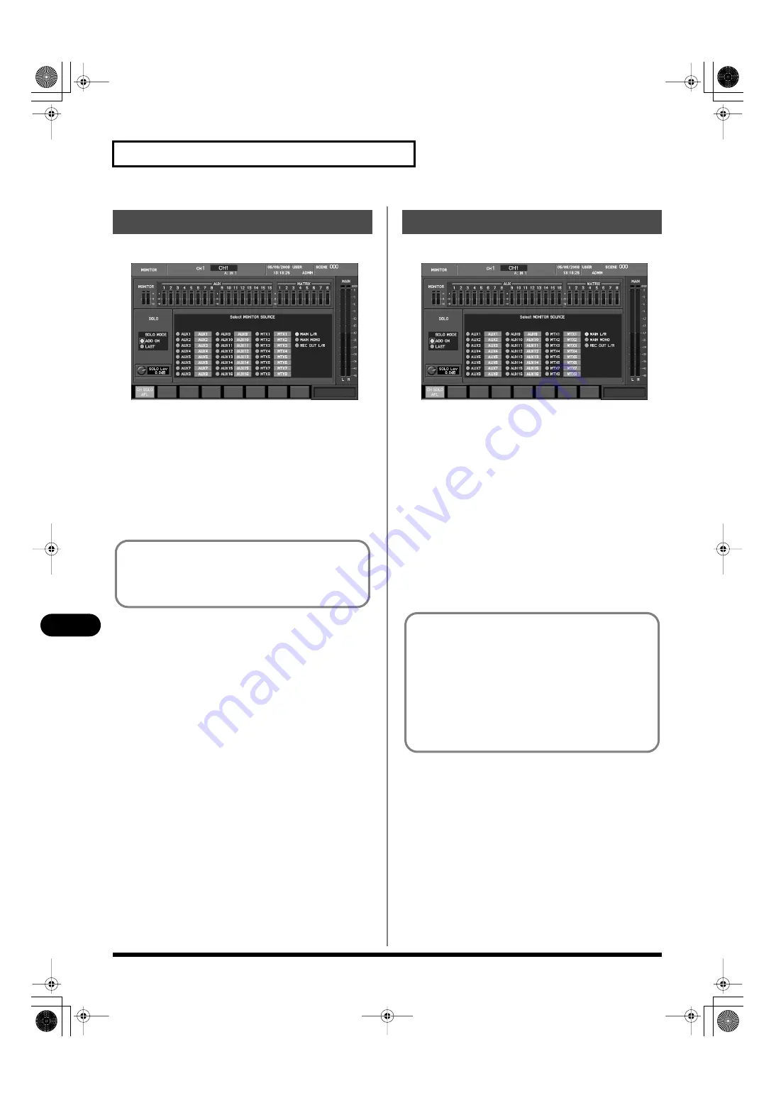
In the top panel MONITOR section, press [DISP].
fig.ScrMonitor.eps
The MONITOR screen will appear.
2.
Use the monitor source select buttons to select the desired
monitor source.
The monitor signal will be output from the output jacks to
which MONITOR OUT L/R are patched, and from the
PHONES jack.
3.
Use the MONITOR section’s LEVEL knob or the PHONES
LEVEL knob to adjust the monitor output level.
1.
In the top panel MONITOR section, press [DISP].
fig.ScrMonitor.eps
The MONITOR screen will appear.
2.
Use the SOLO MODE select buttons to select the desired
solo mode.
3.
Use [F1 (CH SOLO AFL)] to select the point from which the
input channel signal will be sent to solo.
4.
On the top panel, press [SOLO] for the desired channel.
The signal of that channel will be sent to Solo, and output from
the output jacks to which MONITOR OUT L/R are patched,
and from the PHONES jack.
5.
Use the SOLO Lev knob to adjust the solo level.
6.
Use the MONITOR section’s LEVEL knob or the PHONES
LEVEL knob to adjust the monitor output level.
Using Monitor
By default, MONITOR L/R is patched to CONSOLE OUT 7/8
and to DIGITAL OUT. You can use the output patchbay to
change the output destination. For details, refer to “Output
patchbay operations” (p. 118).
Using Solo
If the solo mode is ADD ON, soloing will be controlled so that
input channels, output channels (AUX channels, MATRIX
channels and MAIN L/R channels), and DCA groups are not
soloed at the same time. If the Solo mode is ADD ON, the
selection will be controlled so that the solo signal does not
include both input channels and output channels (AUX
channels and MAIN L/R channel). For example, if an input
channel is soloed, and you turn on Solo for an AUX channel, the
solo setting of the input channel will be defeated and Solo will
be turned on for the AUX channel.
M-400_v15_e.book 156 ページ 2008年6月20日 金曜日 午後4時5分


