45
Basic operation
Basic operation
fig.LayerBtn.eps
Use the buttons of the Layer section to select the channel layer that
will be controlled by the fader module section. Each channel layer
assigns the following channels to the fader module section.
If the user preference AUX/DCA LAYER (p. 178) is set to
“1 8Matrices,” the AUX/DCA layer button will assign
AUX1–AUX16 and MATRIX1– MATRIX8 to the fader module
section.
Here’s how to edit the channel parameters.
1.
In the fader module section or main fader module, press a
[SEL] button to select the channel that you want to control.
fig.SELBtn.eps
2.
In the CHANNEL EDIT section, press [CH DISP].
fig.ChDispBtn.eps
3.
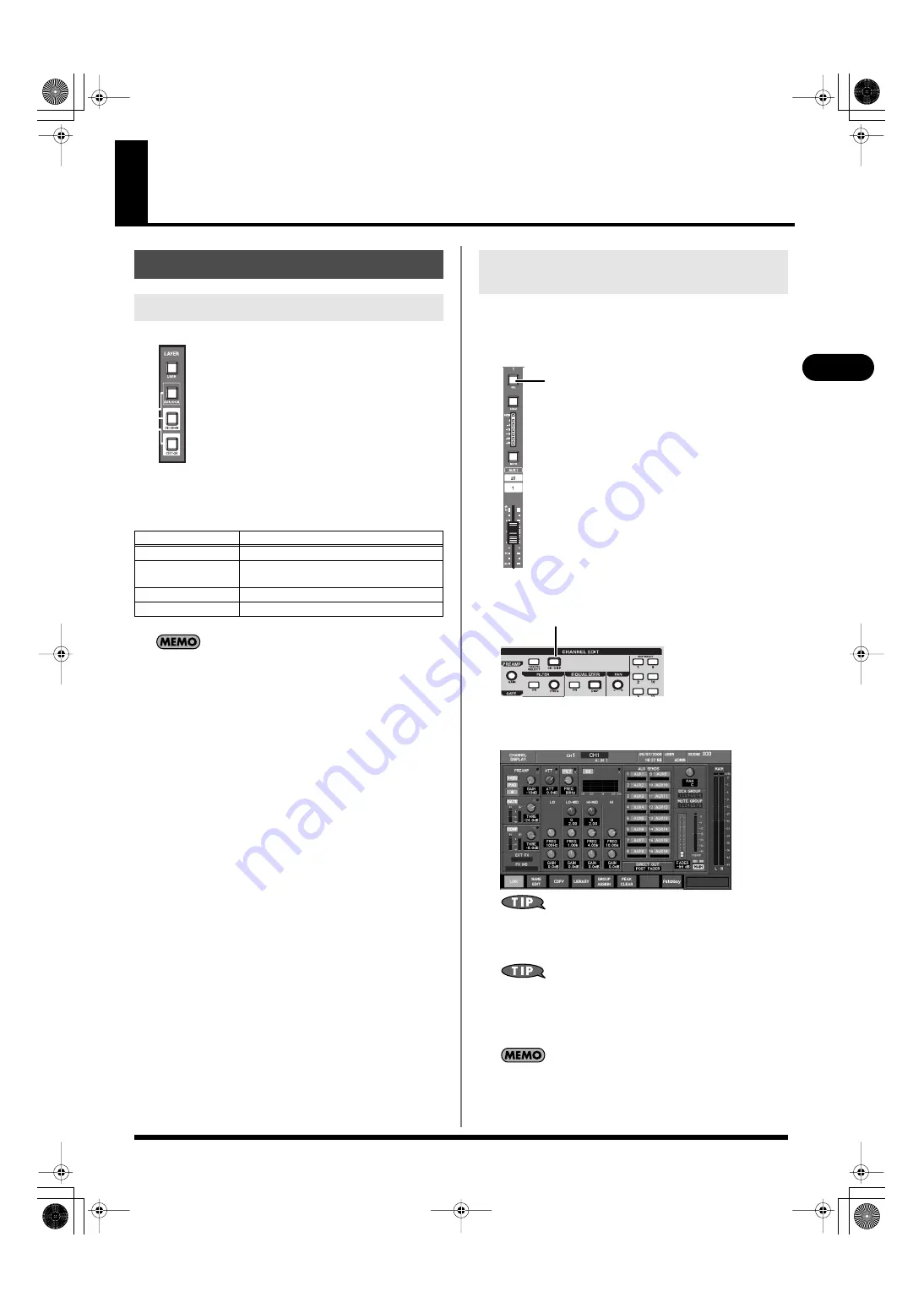
The CHANNEL DISPLAY screen will appear. Use the
controllers of the CHANNEL EDIT section to edit the values.
fig.ScrChDisp.eps
You can make adjustments in finer increments by holding down
[SHIFT] while you operate the CHANNEL EDIT section’s knobs
or the value dial.
If you want to edit channel parameters that are not shown in the
CHANNEL DISPLAY screen, you can press the [DISP] button
in each area of the CHANNEL EDIT section to access a popup
that lets you make settings in greater detail.
If you’ve selected the CHANNEL SELECT item “CHANNEL
DISPLAY follows CH SELECT button” in User Preference (p.
177), pressing a [SEL] button will cause the CHANNEL
DISPLAY screen of that channel to appear.
Basic panel operations
Selecting the channel layer
Channel layer
Channels
USER
USER FADER1–USER FADER24
AUX/DCA
AUX1–AUX16, DCA1–DCA8
(or AUX1–AUX16, MATRIX1–MATRIX8)
CH25-48
CH25–CH48
CH1-24
CH1–CH24
Operations in the CHANNEL EDIT
section
[SEL]
CH DISP
M-400_v15_e.book 45 ページ 2008年6月20日 金曜日 午後4時5分


