background image


  Tuning by Gain Setting 

  8-45


CSD7 Servo Drive (EtherCAT) 


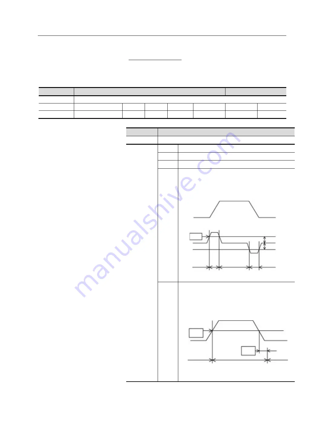
Gain Switching Mode 

 
Gain Switching Mode can be chosen in 0x2006[03] (Ft-0.06[D2]). 
 

0x2006 

Auxiliary Function Selection 1 

CSP 

Sub-Index 3 

Gain Switching Mode 

Setting Range 

Size (Data Type) 

Unit 

Access 

PDO Map 

Attribute 

Init Value 

Ft-no 

0~9 

1 byte(USINT) 

RW 

Always 

0x0 

Ft-0.06[D2] 


Ft-0.06[D2]


Gain Switching Mode 

Range


0~9


Description


0


The 1st gain is fixed (1, 3 group gain).


1


The 2nd gain is fixed (2, 4 group gain).


2


The 2nd gain is used when </G-SEL> signal is input. 

3


When the torque command is higher than the set value, the 
2nd gain is used. 


4


When the velocity  command is higher than the set value, 
the 2nd gain is used. 


Switching level 

Velocity 

Level 

1st 

1st gain 

1st 

Torque 

Switching level 

2nd 

2nd 

Velocity 

Command 

Level 

Delay 

1st 

1st 

2nd gain 

Summary of Contents for OEMax CSD7

Page 1: ...CSD7 Servo Drive User Manual Catalog Number s CSD7_ BN F 1 EtherCAT Network type ...

Page 2: ...ables and requirements associated with any particular installation RS Automation Co Ltd cannot assume responsibility or liability for actual use based on the examples and diagrams Reproduction of the contents of this manual in whole or in part without written permission of RS Automation Co Ltd is prohibited Throughout this manual when necessary we use notes to make you aware of safety consideratio...

Page 3: ...therCAT The revision history of the manual provides the brief description of each manual revision CSD7 UM001A EtherCAT EN Oct 2015 Revision Month Year Manual Version Manual Version Revision Information Revision Date A First edition October 2015 ...

Page 4: ......

Page 5: ...RECAUTIONS P 8 Usage P 8 Storage P 8 Transportation P 9 Installation and Wiring P 9 Maintenance and Repair P 9 CERTIFICATE P 10 CHAPTER 1 BEFORE USING THE CSD7 SERVO DRIVE 1 1 EACH PART NAME OF SERVO DRIVE 1 2 MODEL NUMBER OF THE SERVO DRIVE 1 3 EACH PART NAME OF SERVO MOTOR 1 4 MODEL NUMBER OF THE SERVO MOTOR 1 4 CHAPTER 2 INSTALLATION 2 1 SERVO DRIVE INSTALLATION 2 2 Consideration 2 2 Installati...

Page 6: ...3 15 Sequence Output Signal Allocable 3 17 Allocation Method for Sequence Output Signal 3 18 Notice for Sequence Signal Allocation 3 20 GENERAL I O SIGNAL 3 21 General Input Signal Fixed 3 21 General Output Signal Fixed 3 22 INTERFACE WITH INPUT CIRCUIT OF I O 3 22 Sequence Input Circuit 3 22 Emergency Stop Input 3 23 INTERFAC WITH OUTPUT CIRCUIT OF I O 3 24 Line Drive Output 3 24 Photo coupler Ou...

Page 7: ... 5 Icons for the Key Buttons 4 6 Structure of the Entire Mode 4 7 Status Display Mode 4 8 Parameter Setting Mode 4 10 User Defined Parameter Setting Mode 4 11 Monitor Mode 4 12 BASIC SETTING 4 14 Overview of the Basic Setting 4 14 Control Mode Setting 4 14 STARTUP 4 15 Before Startup 4 15 Startup 4 16 CHAPTER 5 ETHERCAT COMMUNICATION 5 1 ETHERCAT SLAVE INFORMATION 5 2 SET NODE ADDRESS 5 2 Check an...

Page 8: ...9 CHAPTER 6 CIA402 DRIVE PROFILE 6 1 STATE MACHINE 6 2 State Machine 6 2 State Definition 6 3 State Machine Control Command 6 3 Status Display 6 4 Related Object 6 4 MODE OF OPERATION 6 5 Cyclic Synchronous Position Mode CSP mode 6 5 Cyclic Synchronous Torque Mode CST mode 6 7 TORQUE LIMIT FUNCTION 6 9 Related Object 6 10 DIGITAL INPUT OUTPUT 6 11 Related Object 6 11 CHAPTER 7 OBJECT DICTIONARY 7 ...

Page 9: ...U BEGIN 8 2 Mark Description 8 2 Gain Introduction 8 2 Inertia Ratio 8 5 GAIN SETTING BLOCK DIAGRAM 8 8 AUTO GAIN SETTING 8 10 Auto Tuning 8 10 Off line Auto Tuning 8 10 ANF Adaptive Notch Filter Function 8 14 MANUAL GAIN SETTING 8 20 Gain Setting Flowchart 8 20 Basic Gain Setting 8 21 MANUAL GAIN SETTING FOR TORQUE VELOCITY POSITION CONTROL 8 24 Gains Related to Torque Control 8 24 Gains Related ...

Page 10: ...sistor 9 15 SETTING FOR SMOOTH OPERATION 9 17 VELOCITY LIMIT AND VELOCITY LIMIT DETECTION V LMT SIGNAL OUTPUT 9 21 TORQUE LIMIT AND TORQUE LIMIT DETECTION T LMT SIGNAL OUTPUT 9 22 POSITION FEEDBACK TO THE HOST CONTROLLER 9 24 Overview 9 24 Direction Change of Encoder Pulse Output 9 25 Pulse Dividing Circuit 9 26 USE OF ABSOLUTE ENCODER 9 28 What is an Absolute Encoder 9 28 Connecting with Host Con...

Page 11: ...Trigger 1 2 Signal 9 49 CHAPTER 10 INSPECTION AND PROTECTION FUNCTION 10 1 INSPECTION 10 2 Inspection of Motor 10 2 INSPECTION OF SERVO DRIVE 10 3 Part Inspection 10 3 PROTECTIVE FUNCTION 10 4 Servo Warning 10 4 Servo Warning 10 5 Servo Fault 10 6 Confirmation before Requesting for A S 10 11 APPEDIX A SPECIFICATION AND EXTERIOR DIMENSIONS A 1 DRIVE SPECIFICATION A 2 FUSE AND CONTACTOR RECOMMENDATI...

Page 12: ...viii CSD7 Servo Drive EtherCAT SAFETY FUNCTION CONNECTOR B 6 ...

Page 13: ...ve a basic understanding of the CSD7 servo drive contact your local RS Automation sales representative before using this product for information on available training courses About This Publication This manual provides detailed installation instructions for mounting wiring and troubleshooting your CSD7 servo drive and system integration for your drive motor combination with a Motion Card Additiona...

Page 14: ...x Index Object Name Mode of Operation Setting Range Size Data Type Unit Access PDO Map Attribute Init Value Ft no Set Range Size Unit RO RW Possible No Attribute Init Value Parameter No Object with Sub Index Index Object Name Mode of Operation Sub Index 0 Number of Entries Setting Range Size Data Type Unit Access PDO Map Attribute Init Value Ft no Set Range Size Unit RO RW Possible No Attribute In...

Page 15: ...it Indicates the unit of measure of the object Access Indicates whether the object is read only or read and write RO Read Only RW Read and Write PDO Map Indicates the PDO mapping attribute Possible RxPDO Reception PDOs can be mapped Possible TxPDO Transmission PDOs can be mapped No PDs cannot be mapped Attribute Indicates the time during which changes are valid in the writing enabled object Always...

Page 16: ...00 D2 Terminology The following describes terminologies used in this manual Servo Drive or Drive Refer to the CSD7 Servo Drive Servo Motor or Motor Refer to the servo motor exclusively for the CSD7 drive Host Controller Refers to a controller or a device that gives command to the servo drive and controls it Initial Value Refer to the value set at the factory before the shipment Setting Value Refer...

Page 17: ...iagram If I O connector of the servo drive is on the left it is the output of the servo drive 3 If I O connector of the servo drive is on the right it is the input of the servo drive from host controller to the servo drive Example Output I O R1 Host controller 0 V Relay circuit Host controller DC 24V 50mA or above Open collector circuit Host controller DC 24V 50mA or ablove P P i i 24V IN 24V IN S...

Page 18: ...een the side A and B with the connector 5 The following figure shows a symbol used to show a twist pair wires to prevent the noise generation Symbol Figure Description Make a twist pair wires where this symbol is located for the noise prevention 6 The following figure shows a symbol used to show a shield pair wire to prevent the noise generation Symbol Figure Description Shield the wires where thi...

Page 19: ... brief functions of the product 7 Describes the basic settings that users should set 8 Describes the function of the product for each control modes 9 Describes the tuning to implement optimum performance of load system 10 Describes simple supplementary functions 11 Describes the protective function fault diagnosis and troubleshooting 12 Describes items corresponding to various numerical data in th...

Page 20: ...grounded Completely discharged before handling after power off Do not put excessive stress on the motor power and encoder cable Never touch the revolving part of the motor during operation Avoid using the product near wet places or corrosive and inflammable materials Operate the system with no load during pilot operation Never touch the heat sink directly Storage Do not store the product near wet ...

Page 21: ...er to Chapter 2 Maintenance and Repair Do not disassemble or remodel the product Any damage caused after the user disassembles or remodels the product will be excluded from the company s warranty The company bears no responsibility for injuries or physical damage caused by remodeling of this product Life limited Parts by mechanical friction or heat requires regular inspection Refer to the 10 1 pag...

Page 22: ...rds Servo Drive EC Directive EMC Directive EMC Directive 201430 EU KN EN61800_3 KC61800_3 EN61000_4_2 KN61000_4_2 EN61000_4_3 KN61000_4_3 EN61000_4_4 KN61000_4_4 EN61000_4_5 KN61000_4_5 EN61000_4_6 KN61000_4_6 Low Voltage Directive EN61000_5_1 USA Standards NRTL UL508C Canada Standards NRTL C C22 2No 14_10 ...

Page 23: ...Preface P 11 CSD7 Servo Drive EtherCAT ...

Page 24: ......

Page 25: ...o Drive This chapter describes the general matters and optional specifications that you should know before using the CSD7 SERVO DRIVE EACH PART NAME OF SERVO DRIVE 1 2 MODEL NUMBER OF THE SERVO DRIVE 1 3 EACH PART NAME OF SERVO MOTOR 1 4 MODEL NUMBER OF THE SERVO MOTOR 1 4 ...

Page 26: ...nector ECAT IN EtherCAT Connector Safety Safety Connector Only supported in premium models I O Input Output Signal Connecror ENC Motor Encoder Signal Connector Drive Name Plate B1 B2 External Regenerative Resistor Connector U V W Motor Power Cable Connector ENC AUX Auxiliary Encoder Signal Connector Only supported in premium models ECAT OUT EtherCAT Connector L1 L2 Main Power Connector 400W Under ...

Page 27: ...the serial number during the use Table 1 Product Classification Classification Available Operation Modes Special Function Basic model CSP Cyclic Synchronous Position mode CST Cyclic Synchronouse Torque mode Preminum model CSP Cyclic Synchronous Position mode CST Cyclic Synchronouse Torque mode Full Closed Loop Control STO Safety Torque OFF Function Drive Series Product Classification Drive Type Ra...

Page 28: ...anual Publication SMOTOR UM002 Model Number of the Servo Motor The following figure describes the model name of the motor on the nameplate Motor Brake Cable Motor 3 phase Power CAble Encoder Cable Encoder Motor Frame Motor Shaft Motor Fixing Hole Note R 17bit Incremental Motor Series Des Order Motor Shaft Spec Encoder Type Option Input Voltage V Rated Output W CSMT Series 50W 800W CSMR Series 50W ...

Page 29: ...s matters to consider when installing the servo drive and the motor Refer to the Exterior Dimension and Mouning Dimension on page A 4 for the dimension of the servo drive and the peripheral parts relevant to the installation SERVO DRIVE INSTALLATION 2 2 SERVO MOTOR INSTALLATION 2 9 ...

Page 30: ...ace Be sure to install the product vertically Install the Servo Drive Vertically The CSD7 series servo drive adopts a forced cooling method using the fan installed inside the product To increase cooling efficiency be sure to install the product vertically As the servo drive includes electronic parts which are sensitive to static electricity install the product in an environment in which static ele...

Page 31: ...on about the drive dimension please refer to the page A 4 Exterior Dimension and Mouning Dimension WALL MOUNT Fixing Bolt All model One M4 x L10 bolt for top and bottom Apply M4 bolt to both top and bottom For more detailed information about the drive dimension please refer to the page A 4 Exterior Dimension and Mouning Dimension Fixing bolt Fixing bolt Fixing bolt Fixing bolt Fixing bolt Fixing b...

Page 32: ... case of zero stacking installation attach an external fan to keep the ambient temperature of the products below 40 degrees Celsius 30 0 mm 1 18 in Adjacent Wall Top of Drive 100 mm Bottom of Drive 50 0 mm 1 97 in Installation by 10mm intervals 30 0 mm 1 18 in Adjacent Wall Top of Drive 100 mm Bottom of Drive 50 0 mm 1 97 in Installation by Zero Stacking ...

Page 33: ...Installation 2 5 CSD7 Servo Drive EtherCAT 100W 200W 400W 800W 1KW 1 5KW ...

Page 34: ...s product should be used at IP2x so use the product in a clean environment without dust or humidity Ground Product There is a grounding terminal at the bottom of the heat sink 100w 1 5Kw All model Two M4 bolts for input power motor power grounding If not grounded it may reduce the performance Be sure to connect the ground of input power and motor power to the grounding terminal of the drive ...

Page 35: ... without condensations Vibration 5 55Hz 0 35mm 0 014 double amplitude continuous displacement 55 500Hz 2g peak constant acceleration Installation place Installation place must meet the following conditions IP2X Pollution level 2 Indoors Well ventilation Easy checkup Without explosive gas IP2x Pollution level 2 AC 220V 3 phase 50Hz 60Hz Fuse or Circuit Breaker 1 1 Insulating Transformet Drive AC li...

Page 36: ...installed close to the drive as much as possible 5 The regenerative circuit is available only for the product of 400W and above CSD7_04Bxx1 CSD7_15Bxx1 For the product of 200W and below CSD7_01Bxx1 CSD7_02Bxx1 the B1 and B2 terminal should be kept with nothing connected 6 For the high frequency ground a thick braided wire is connected among the product equipment enclosure machine frame motor and g...

Page 37: ...single phase is applied Ferrite Core Wire for AC power Motor power Encoder signal OP14 2x28 5 6 8H Wire for I O communication USB RS485 OP12x20 5 6H To maintain reliability for a long time use it within from 0 to 35 Install a serperate cooling device at a place with high ambient temperature and use it within the operating temperature 0 50 Servo Motor Installation For the motor dimension related to...

Page 38: ......

Page 39: ... to the servo drive along with the circuit diagram BEFORE YOU BEGIN 3 2 POWER SUPPLY MOTOR POWER REGENERATIVE RESISTOR 3 5 I O SIGNAL I O 3 11 SEQUENCE I O SIGNAL 3 13 GENERAL I O SIGNAL 3 21 INTERFACE WITH INPUT CIRCUIT OF I O 3 22 INTERFAC WITH OUTPUT CIRCUIT OF I O 3 24 SPECIFICATION OF STO SAFE TORQUE OFF 3 26 ENCODER WIRING 3 29 GENERAL ARTICLES WIRING 3 31 ...

Page 40: ...y the qualified person High voltage remains in the drive even through the power is off Therefore do not inspect components unless inside Charge Lamp goes out completely Pay attention to the polarity when wiring The heatsink of the drive generates high temperature Pay attention to wiring the cables not to pass by near the heatsink CAUTION ...

Page 41: ...unctional Safety function STO Safety Torque Off 5 I O Input Output function composed of 20 pins 6 ENC Input the serial encoder signal of the motor used 7 ENCAUX Connector for the external linear scale used for the full closed function Built in Operator USB RSware Connector ECAT IN EtherCAT Connector Safety Safety Connector Only supported in premium models I O I O Signal Connector ENC Motor Encoder...

Page 42: ...cted to the CSD7 drive to allow normal operation When Using a Safety Switch When Using a Safety Sensor When Multiple Drives are Connected to a Single Safety Sensor Safety Sensor Servo Amp Contact Output Safety Input Safety Input EDM Output 24V 0V SFI1 SFI1 SFI2 SFI2 EDM EDM EDM Output EDM Input Safety Sensor Safety Output Source EDM Output SFI1 SFI1 SFI2 SFI2 EDM EDM Control Output 2 Control Outpu...

Page 43: ...g terminal of the drive Regenerative Register Connector B1 B2 200W and lower As the function for regenerative energy consumption is not required the regenerative resistor does not have to be mounted 400W and higher If the capacity of the mounted regenerative resistor is insufficient connect an external resistor with a larger capacity in a parallel manner to the regenerative resistor connector B1 a...

Page 44: ...of the main power The user can take appropriate action after identifying the cause of cut off of the main power Refer to the 3 7 page Electric Circuit Diagram for the Electric Circuit Diagram of the power separation Motor Power Cable Connector U V W The motor power cable connector U V W is output terminal Do not connect the input power It may cause the drive damage Regenerative Resistor Connector ...

Page 45: ...input filter and shielded motor power signal cable are used and the ferrite core should be used in the AC power line motor power signal line input output and communication USB RS485 cable As the AC power input filter has a large leakage current discharge time is required after removing the power supply The wiring between drive and filter should be kept as short as possible The common ground bar sh...

Page 46: ...2 8 It is a DC voltage connection terminal Connect the DC power supply which has the circuit limiting the initial charging input current to the B1 and DC terminal 9 The heatsink on the drive has two screws for ground connection of motor and input power respectively The ground screw should be tightened to 1 25 Nm 11 lbs in torque 10 As for the installation environment the product should be installe...

Page 47: ...an 8 mm The use of phenol terminal is recommended for the reliability of wiring After connecting the wire pull it slightly to check if the connection between the socket and wire is normal You can disconnect the wire by pressing the button at the top of the socket The thickness of wire allowed by the socket is shown below Table 6 Thickness of wire Rated Power Wire Thickness 400W and less AWG26 AWG1...

Page 48: ...3 10 Wiring CSD7 Servo Drive EtherCAT Insert the wire completely If peeled core wire is exposed it may cause an electric shock CAUTION ...

Page 49: ...ry for absolute encoder does not have the separate terminal It must be connected at motor encoder cable side COM_GND INPUT1 ENABLE INPUT2 P OT INPUT3 N OT INPUT4 HOM SEN E STOP TP_24V TP_GND Touch_probe_1 Touch_probe_2 OUTPUT1 OUTPUT1 OUTPUT2 OUTPUT2 OUTPUT3 BK OUTPUT3 BK EA EA EB EB Encoder Output A B phase Sequence Output Touch probe input Input Output 20 pin Connector I O Sequence Input Output ...

Page 50: ...6 INPUT2 Digital input 2 P OT 1 7 INPUT3 Digital input 3 N OT 1 8 INPUT4 Digital input 4 HOME 1 9 E STOP Emergency Stop Initial value Disable 1 10 Signal GND Encoder Signal Output Ground Common GND for Pin No 11 14 Pin No Signal Symbol Description 11 EA Encoder Signal Output A 12 EA Encoder Signal Output A 13 EB Encoder Signal Output B 14 EB Encoder Signal Output B 15 OUTPUT 1 Digital Output 1 16 ...

Page 51: ...u can freely allocate output signal of each function with three pairs of pins such as pin No 15 16 17 18 and 19 20 of I O Sequence I O signal means the I O signal of various functions that are required for the sequence control of the servo drive by the host controller Sequence I O signal is not to process input or output signal with the fixed pin of I O but to select the function that the user req...

Page 52: ...witching G SEL Function P TL Positive Torque Limit When it is set to ON the forward torque is limited by the 0x2409 Ft 4 09 All N TL Negative Torque Limit When it is set to ON the reverse torque is limited by the 0x240A Ft 4 10 All P OT Positive Over travel It prohibits the motor from rotating forward when the motor load reaches the limit of the available section All 9 3 page Overtravel Input P OT...

Page 53: ...ll the time regardless of the wiring set the related digit of the parameter to b Table 9 I O Sequence Input Signal Allocation Setting Value b 4 3 2 1 0 Input Channel No Always Valid INPUT 4 INPUT 3 INPUT 2 INPUT 1 Always invalid I O Pin No 8 7 6 5 The following table describs each digit of the parameters for sequence input signal allocation Set the digit of the parameter to the right value custome...

Page 54: ...3 Ft 0 19 Reserved Reserved Reserved Reserved The table below is the example to allocate sequence input singal Table 11 Example for Sequence Input Configuration Configuration Example Index Setting 0x200A 02 2 Built In Setting Ft 0 10 D1 2 The second sub index of 0x200A is set to 2 or the second digit of Ft 0 10 is set to 2 This value is intended to allocate the P OT input function and 2 is set her...

Page 55: ...the motor is higher than the value of the Rotation Detection Level 0x2212 Ft 2 19 All T LMT Torque Limit Detection This signal turns ON when the feedback torque of the motor reachs the value of the Torque Limit All 9 22page Torque Limit and Torque Limit Detection T LMT signal output V LMT Speed Limit Detection This signal turns ON when the feedback speed of the motor reachs the value of the Speed ...

Page 56: ... signal is not used Table 13 Sequence Output Signal Allocation 설정값 3 2 1 0 Output Chanel No OUTPUT 3 OUTPUT 2 OUTPUT 1 Always Invalid I O Pin No 19 20 17 18 15 16 The following table describs each digit of the parameters for sequence output signal allocation Set the digit of the parameter to the right value customer want to use Table 14 Digit of Parameter for Sequence Output Index Parameter Digit ...

Page 57: ... 15 Example for Sequence Output Configuration Allocation Example Object Setting 0x2016 03 3 Built In Setting Ft 0 22 D2 3 The 0x2016 03 or Ft 0 22 D2 is the index for allocation of BK function The meaning of 3 in the 3rd digit of the index is that OUTPUT3 pin no 19 and 20 of I O connector will be used as BK output function Applicable Modes All Other Details Servo off Configuration Completed ...

Page 58: ... described above the servo warning is indicated Status Display Mode PIn In this case when you reapply the power after completing the input allocation servo warning Pin is indicated in the Status Display Mode Check if you allocate more than two functions to the same pin of I O You can check the status of the sequence I O signal through Monitor mode function on page 9 42 Unlike the sequence input th...

Page 59: ...s 21 6 26 4V 210mA All The common terminal for 3 4 pin of 20 pin I O connector Emergency Stop Table 17 Emergency Stop Input Signal Name Symbol Pin No Function Operation Mode Details Emergency Stop E STOP Pin 9 Connect this signal to an extra emergency stop switch and use it to quickly act upon emergency situation User can select whether to use in 0x2005 04 or Ft 0 05 D3 0 Disable 1 Enable All 3 23...

Page 60: ...e of 0x2300 03 or Ft 3 00 D2 All 9 24 page Position Feedback to the Host Controller EA Pin 12 EB Pin 13 EB Pin 14 Interface with Input Circuit of I O The following describes the connecontion circuit for input from the host controller to the servo drive Sequence Input Circuit Relay or open collector output of the host controller is used for the sequence input circuit Make sure that the input curren...

Page 61: ...The initial value is set as not to use Factory initial 0x2005 04 Ft 0 05 D3 0 So if you want to use this input signal set this value to 1 The 9 pin of I O is used as the input pin only for the emergency stop If the emergency stop signal is entered servo fault E EStoP is generated For more information about the servo fault refer to the 10 4 page Protective Function If the emergency stop is released...

Page 62: ...al data into 2 phase A phase and B phase pulse are transmitted through line drive circuit It is used to configure the position control loop in the host controller Receive the pulse signal with the line receiver circuit in the host controller Set the value of R1 to 330 Ω Photo coupler Output The sequence output signals are transmitted from photo coupler output circuits of the drive In case of conne...

Page 63: ...nnection to the relay circuit of the host controller In case of connection to the line receiver circuit of the host controller P I O 0V DC 5 24V Host controller Relay Terminal resistor should be connected P I O 0V DC 5 12V Host controller Line receiver ...

Page 64: ...to terminal is turned on Non Safety state P C connected to terminal is turned off 4 Input SFI1 3 Input SFI2 Safety State Input 2 Shut off 2 Safety state P C connected to terminal is turned on Non Safety state P C connected to terminal is turned off 6 Input SFI2 5 Input EDM Safety Circuit Status Output Open Collector Safety state It is turned on between two pins Non Safety state It is turned off be...

Page 65: ...f is maximum 1 msec and the time T2 taken until the torque is off is maximum 0 5 ms EDM External Device Monitor It is used as a safe state output signal SFI1 SFI2 EDM Motor Torque Drive Enable T2 T1 T1 T1 Max 1 0ms T2 Max 0 5ms STO Wiring Connecting to Safety Switch Safety Sensor Servo Amp Contact Output Safety Input Safety Input EDM Output 24V 0V SFI1 SFI1 SFI2 SFI2 EDM EDM ...

Page 66: ...tput Source Safety Input Safety Input EDM Output Control Output 1 0V SFI1 SFI1 SFI2 SFI2 EDM EDM 24V EDM Input Control Output 2 EDM Output EDM Input Safety Sensor Safety Output Source EDM Output SFI1 SFI1 SFI2 SFI2 EDM EDM Control Output 2 Control Output 1 Servo Amp EDM Output SFI1 SFI1 SFI2 SFI2 EDM EDM Servo Amp SFI1 SFI1 SFI2 SFI2 EDM EDM Servo Amp ...

Page 67: ...ir 2 5 SD 3 7 VCC 5V 4 8 COM 0V 5 N C 6 N C F G 3 F G Encoder Connector Specification The following figure and table describe the connector specification of encoder cable CON A Connector for connection to the ENC of servo drive Table 25 Encoder Connector Specification Catalog number Manufacturer 3E206 0100KV Connector 3E306 3200 008 Assembly 3M The one kind of connector as listed above is used in ...

Page 68: ...0365 1 AMP Power cable connector for large capacity motor packed with the motor Do not connect FG of servo drive to host controller if GND and FG are common or if there is no separate FG Connection Diagram of Encoder Signal BAT Connection for the Use of Absolute Encoder Host Controller Motor Encoder Output CSD7 ENC I O 13 EB 14 EB P 10 SG 0 V 0 V SD 1 SD 2 4 5 P E5 V 3 E0 V 4 7 8 P FG FG 3 P BAT 1...

Page 69: ...lter for the main power and control power Electric circuit wiring and signal circuit wiring should be apart from each other as much as possible Min 30 cm or more Do not use same power with the electric ARC welding machine or electric spark machine The earth wire of the servo motor must be connected to the grounding terminal of the drive In addition connect the grounding terminal of the drive to th...

Page 70: ...urge suppressor to the relay solenoid and coil of the magnetic contactor Fuse selection for the Drive The table below shows the recommened capacity of fuse for each servo drive Table 27 Recommened Fuse Capacity Drive Powr rating Rated Power of Drive kVA MCCB or Fuse Power capacity A CSD7_01BN1 CSD7_01BNF1 100 W 0 23 4 CSD7_02BN1 CSD7_02BNF1 200 W 0 45 4 CSD7_04BN1 CSD7_04BNF1 400 W 0 89 8 CSD7_08B...

Page 71: ...al circumstances Noise Protection The high speed switching device and microprocessor are used at the main circuit of the CSD7 servo drive Thus switching noise is affected by the connection and grounding methods Use the proper wiring and grounding method to prevent any affects from the noise Use a wire of 3 5 or thicker for the earth wire Separate the signal and power wiring CAUTION CAUTION ...

Page 72: ...e following figure describes precautions when wiring the noise filter If the wiring is wrong the performance of the noise filter falls Relay Sequence Generating Circuit Servo Motor I O 방열판 L1 L2 L3 L1C L2C U V W Ground Plate One Point Grounding Class 3 Grounding or Under Earth Grounding LINE FILTER 1 LINE FILTER 2 AVR PG M ...

Page 73: ...uld be wired in distance to the output wire and do not put other signal lines and earth wire in a same duct and tie up them together 1 2차 간섭 1 2차 간섭 회로 분리 회로 분리 FILTER 1st 2nd FILTER 1st 2nd FILTER 1st 2nd FILTER 1st 2nd 1st 1st 2nd 2nd FILTER 1차 2차 FILTER 1차 2차 1차 1차 2차 2차 1st and 2nd Interference 1st and 2nd Interference Circuit Separation Circuit Separation ...

Page 74: ... inside of the case to the grounding plate And then ground them Wiring When Multiple Drives Are Used This is an example of wiring when connecting several drives Connect the sequence output RDY signal of each servo drive in a series and run Relay 1 to detect the fault Normally OUTPUT and OUTPUT are interconnected and with 24 V supplied to Relay1 the servo drive runs normally If the servo fault is g...

Page 75: ...ameter The initial value of this parameter is set as not to use 0x2005 04 Ft 0 05 D3 0 Do not wiring if it does not using the emergency stop Note 알람 표시용 Lamp Note Note Note Indicating Lamp for Servo OFF Note Note Note L1 L2 L1C L2C L3 I O RDY 1 24 V IN E STOP 15 1 9 16 L1 L2 L1C L2C L3 I O RDY 1 24 V IN E STOP RDY 1 15 1 9 16 L1 L2 L1C L2C L3 I O RDY 1 24 V IN E STOP RDY 1 15 1 9 16 1MC NOISE FILT...

Page 76: ......

Page 77: ...asic Setting and Commissioning This chapter introduces the operator mounted on the servo drive In addition it describes the basic setting of servo drive and also an example for simple startup BEFORE YOU BEGIN 4 2 OPERATOR 4 5 BASIC SETTING 4 14 STARTUP 4 15 ...

Page 78: ...nd play music and display channel that the users want from the moment the power switch is on However the servo drive cannot run servo motor by simple applying the power To complete load the system and use the servo drive Servo ON signal from the host controller is required Servo ON signal should be applied and maintained from the host controller for the servo drive to run the motor In servo OFF st...

Page 79: ...is not applied after the power application it is same as the servo driver and motor being separated completely This is a ready status to run the motor If the ENABLE signal is input and the servo ON signal is applied from the host controller the drive is ready to run the motor At this time if there is no command for the motor rotation the drive maintains the motor in the stop control state If the m...

Page 80: ...is described in the 4 16 page Startup run 00 run 01 run 08 run 10 run 12 are not operated in Servo ON status Servo ON function is not operated in OP Mode of EtherCAT communication Servo Fault and Status If servo fault is occurred by the self diagnosis function of the drive while the Servo ON signal is applied to the drive the drive make itself Servo OFF to stop the motor and displays the contents ...

Page 81: ...servo drive is in servo ON status or servo OFF status Operator Name and Function of Each Part The servo drive has a built in operator for various status displays parameter setting operation command and monitoring Displays various contents with six 7 segment LED display Provides all key manipulation function without a separate external operator The following figure shows the front side of the opera...

Page 82: ...sed for applying the setting value Same function as the Set Mode key of existing CSD3 5 Up The value or parameter is increased by 1 from the cursor position for bit field fixed to max value of each bit Generally if the Up key is pressed at 9 carry applies Long pressing speeds up the increase in value Down The value or parameter is decreased by 1 from the cursor position for bit field fixed to min ...

Page 83: ...the status display mode Mode is changed whenever the MODE SET key is pressed Be fully aware of the following 5 types of modes and read the following The displayed values in the above figure are the initial value of each mode If the value is changed in a mode and then returned the changed value is shown instead of the initial value Status Display Mode Parameter Set Mode User Parameter Mode Monitor ...

Page 84: ...rol Mode Display Item Display Description Basic Control Mode CSP mode CSP Cyclic Synchronous Position CST mode CST Cyclic Synchronous Torque Status The Status indicate the following states of servo drive 1 Servo OFF Servo ON status display 2 P OT N OT status display 3 Warning and Fault status display The display priority is 3 2 1 When a servo warning or a fault goes off a relevant alert message is...

Page 85: ... 3rd Dot The 0 3rd dot keeps repeating ON OFF when the Servo is ON These dots are turned OFF when the Servo is OFF 1st 2nd 3rd row Table 32 Meaning of the each row row Description 1st row It is on while P COM signal is output When using as CSP mode if the difference between actual position and position command is smaller than the set value of 0x2312 Ft 3 18 the servo drive output P COM signal P CO...

Page 86: ...the functional description of the servo drive The table below is to aid the understanding of parameter group Parameter range Ft 0 00 Ft 5 13 Table 33 Parameter Group Parameter Group Description Group 0 0x2000 0x2021 Ft 0 00 Ft 0 33 User parameter related to basic setting and I O signal Group 1 0x2100 0x2116 Ft 1 00 Ft 1 22 User parameter related to gain and gain tuning Group 2 0x2200 0x2218 Ft 2 0...

Page 87: ...ater and in the chapter 7 along with the functions of the servo drive Table 34 User defined Parameter Group Parameter Group Description Same Parameter UF 0 03 Off line Auto Tuning Function Selection Ft 0 03 UF 1 01 System Gain Ft 1 01 UF 1 02 1st Proportional Gain in Speed Loop Ft 1 02 UF 1 03 1st Integral Gain in Speed Loop Ft 1 03 UF 1 07 1st Proportional Gain in Position Loop Ft 1 07 UF 4 02 1s...

Page 88: ... Unit 0x2A00 dIS 00 Velocity feedback rpm or mm sec 0x2A01 dIS 01 Velocity command rpm or mm sec 0x2A02 dIS 02 Velocity error rpm or mm sec dIS 03 Torque command dIS 04 Position feedback pulse dIS 05 Position command pulse dIS 06 Position error pulse dIS 07 Position command frequency kpps 0x2A08 dIS 08 Electrical angle 0x2A09 dIS 09 Mechanical angle 0x2A0A dIS 10 Accumulated load factor of regener...

Page 89: ... a special function which can be used Just as in the parameter setting mode there is a status where the operation is possible impossible according to the status of the servo drive during the use of the operation mode Refer to the 9 34 page Operation Mode Function for details of operation mode The table below shows the brief functions of each item in the operation mode Operation Mode Range run 01 r...

Page 90: ...e not changed even if the power is cut off after editing parameter or parameter is initialized by run 12 function of the operation mode To change basic setting value change it directly from corresponding parameter and reapply the power Table 37 Basic Setting No Basic Setting Parameter Description Ft 0 00 Control mode setting Optional Control Mode Setting Control Mode Type As in the table below CSD...

Page 91: ... on the equipment remove coupling of the motor shaft so that load may not move Cautions when Startup To prevent the injury during operation check the operation range of the motor shaft or load and keep it away from the motor load Run the drive after preparing the E stop circuit Then you can cope quickly with an emergency situation For more information about E stop refer to Emergency Stop Input on ...

Page 92: ...eration speed is 50 rpm At startup 1 runs the drive at the factory setting speed 50 rpm Start up the drive according to the following flowchart Status Display Mode Comminssioning Flow Chart for Jog Operation run 00 Select Operation Mode With MODE SET key Press the Enter key to check the jog operation Select run 00 using direction keys Press MODE SET key to prepare JOG ON Press the Enter key to end...

Page 93: ...e Jog operation speed by according to the following flowchart ㅌ If setting is wrong the setting window does not blink when saving it by pressing the MODE SET key If setting is completed normally retry the Jog operation run 00 You can see that the speed is changed from 50 rpm to 1000 rpm Status Display Mode Flow Chart for Changing the Jog Speed Power ON Select the parameter setting mode with MODE S...

Page 94: ......

Page 95: ...o use EtherCAT communication for using EtherCAT network type CSD7 ETHERCAT SLAVE INFORMATION 5 2 SET NODE ADDRESS 5 2 REFERENCE MODEL 5 5 STRUCTURE OF CANOPEN OVER ETHERCAT 5 7 ETHERCAT STATE MACHINE ESM 5 8 PDO PROCESS DATE OBJECT 5 11 SDO SERVICE DATE OBJECT 5 17 SYNC BY DISTRIBUTED CLOCK DC 5 18 ...

Page 96: ...er the simpler way is to check and set in the status display mode of Built In Operator at the front when the AC power of the servo drive is turned on In the status display mode press and hold the SET key for about 1 second then move to the setting mode of Ft 0 33 2 When using Host controller Check and change node addresses in Index 0x2021 After changing node addresses in 0x2021 you must send the c...

Page 97: ... changing of the network wiring When a value from 1 255 is set this address can be used to configure the node in the Master If you configure the node address using this address in the Master this address is going to be the node address of the servo drive You can also set it so that the node address of servo drive is not changed even when the network wiring changes depending on the Master Our Ether...

Page 98: ...on error or communication data error Double Flash Watchdog timeout error on the EtherCAT communication Flickering Boot error On PDI watchdogn timeout error L A 1 Green Off Link is not established in physical layer On Link is established in physical layer Flickering In operation after establishing link L A 2 Green Off Link is not established in physical layer On Link is established in physical laye...

Page 99: ...ation Application layer SDO Service Data Object Mailbox PDO Process Data Object ESM EtherCAT State Machine ESI Slave Information Interface 6 Presentation Presentation layer Empty 5 Session Session layer 4 Transport Transport layer 3 Network Nwtwork layer 2 Data link Data link layer SM Sync Manager FMMU1 Fieldbus Memory Managerment Unit PDI Process Data Interface DC Distributed Clock 1 Physical Phy...

Page 100: ...ng Layer 4 Transport layer Provides transarent reliable data transfer end to end transfer across a network which may include muliple links Layer 5 Session layer Creates and manages dialogue among lower layers Layer 6 Presentation layer Converts data to from standardized network formats Layer 7 Application layer Translates demands placed on the communication stack into a form understood by the lowe...

Page 101: ...tents of process data are defined by PDO mapping The process data communication reads and writes PDOs periodically and the mailbox communication SDO an asynchronous message communication can read and write all object dictionaries Servo drive EtherCAT Data Link Layer Mailbox Process Data DL Control DL Status DL info Slave Address FMMU 1 FMMU 2 FMMU 3 FMMU n Physical Layer Application CiA 402 Device...

Page 102: ... PDO Communication in the ESM state Status SDO Communication PDO Reception PDO Transmission Descriptions Init Disabled Disabled Disabled This is the initialization state of communication unit Communication cannot be carried out Pre Operational Enabled Disabled Disabled Only mailbox communication is available After initialization this state processes the initial settings of network Safe Operational...

Page 103: ... Off run 00 Auto Tuning run 01 EtherCAT communication cable open Operated Operated Operated Init state Operated Operated Operated Pre Operational state Not operated Not operated Not operated Safe Operational state Not operated Not operated Not operated Operational state Not operated Not operated Not operated Table 44 Description of ESM State Transition State Transition Description IP Start Mailbox...

Page 104: ...T protocol When firmware downloading is completed the Bootstrap state is shifted into the Init state in which there is no risk Make sure that the power is not turned off during downloading The considerations required for firmware to be used with no risk are given below Check the message of firmware download completion at the servo drive Check if a voltage alarm for the control power has been gener...

Page 105: ... Object Dictionary to PDO The number of mapped objects is recorded in Sub index 0 of the mapping table CSD7 uses 0x1600 0x1604 for RxPDO mapping and 0x1A00 0x1A04 for TxPDO mapping Each of them has fixed PDO mapping parameters The following figure provides an example of PDO mapping 0x1A0y TxPDO Mapping Example Sub Index Data 32 bit Name 0 5 Number of Entries 1 0x6064 0x00 0x20 Position actual valu...

Page 106: ...written in Sub index 0 of the Sync Manager PDO Assign table In this table Index 0x1C12 is for RxPDO and 0x1C13 for TxPDO The following figure provides an example of Sync Manager PDO mapping Sync Manager PDO Assign Object Index Sub Object contents 0x1C1z 1 0x1B00 0x1C1z 2 0x1B01 0x1C1z 3 0x1B03 0x1C1z 4 0x1B06 Mapping Object 0x1B00 PDO A 0x1B01 PDO B 0x1B02 PDO C 0x1B03 PDO D 0x1B04 PDO E 0x1B05 PD...

Page 107: ...be function INT 4 0x60FE Digital Outputs UDINT RxPDO 2nd RxPDO Mapping 0x1601 3 2 0x6040 Control word UINT 4 0x607A Target Position DINT 4 0x60FE Digital Outputs UDINT RxPDO 3th RxPDO Mapping 0x1602 3 2 0x6040 Control word UINT 4 0x60FF Target Velocity DINT 4 0x60FE Digital Outputs UDINT RxPDO 4th RxPDO Mapping 0x1603 3 2 0x6040 Control word UINT 2 0x6071 Target Torque INT 4 0x60FE Digital Outputs...

Page 108: ...orque actual value INT 4 0x60F4 Following error actual value DINT 2 0x60B9 Touch Probe Status UINT 2 0x603F Error Code UINT 4 0x60FD Digital Inputs UDINT TxPDO 3th txPDO Mapping 0x1A02 4 2 0x6041 Status Word UINT 4 0x6064 Position Actual Value DINT 2 0x603F Error Code UINT 4 0x60FD Digital Inputs UDINT TxPDO 4th txPDO Mapping 0x1A03 4 2 0x6041 Status Word UINT 2 0x6077 Torque actual value INT 2 0x...

Page 109: ...er Definition 2nd User Definition 10th User Definition RxPDO 3th RxPDO Mapping 0x1702 Max 10 1st User Definition 2nd User Definition 10th User Definition RxPDO 4th RxPDO Mapping 0x1703 Max 10 1st User Definition 2nd User Definition 10th User Definition RxPDO 5th RxPDO Mapping 0x1704 Max 10 1st User Definition 2nd User Definition 10th User Definition TxPDO Mapping Table PDO Map PDO Map_Name Number ...

Page 110: ... Type 10th User Definition TxPDO 3th txPDO Mapping 0x1B02 Max 10 1st User Definition 2nd User Definition 10th User Definition TxPDO 4th txPDO Mapping 0x1B03 Max 10 1st User Definition 2nd User Definition 10th User Definition TxPDO 5th txPDO Mapping 0x1B04 Max 10 1st User Definition 2nd User Definition 10th User Definition ...

Page 111: ...known 0x05040005 Out of memory 0x06010000 Unsupported Access 0x06010001 Write only entry 0x06010002 Read only entry 0x06010003 Entry can not be written because Subindex0 is not 0 0x06010004 The object can not be accessed via complete access 0x06020000 Object not existing 0x06040041 Object can not be mapped to PDO 0x06040042 Mapped Object exceeds PDO 0x06040043 Parameter is incompatible 0x06040047 ...

Page 112: ... Master and Slave share the reference clock system time for sync and an interrupt Sync0 that is generated by the reference clock occurs in the Slave CSD7 supports the DC Synchronous mode DC Synchronous Mode In the DC Synchronous mode drives are synchronized by Sync0 signals of the EtherCAT Master Communication Cycle DC Cycle The communication cycle is determined by setting the output cycle of Sync...

Page 113: ... Master and the Slave Master Slave Master Application Master Application U U U Frame U Master user shift time Frame U Cycle time 0x1C32 02 Cycle time 0x1C32 02 Sync0 Event Sync0 Event Sync0 Event Sync0 shift time Shift time 0x1C33 03 Cal Copy time 0x1C33 06 Input Latch Shift time 0x1C32 03 Output Latch Cal Copy time 0x1C32 06 ...

Page 114: ......

Page 115: ...rive Profile CSD7 Servo Drive was designed based on the CIA402 Drive Profile of EtherCAT This Chapter describes the CIA402 drive profile to control CSD7 Servo Drive STATE MACHINE 6 2 MODE OF OPERATION 6 5 TORQUE LIMIT FUNCTION 6 9 DIGITAL INPUT OUTPUT 6 11 ...

Page 116: ... the same time the Servo Drive is run with one master command from Ready to switch on through Switched on to Operation enable B Torque Torque on the motor enabled B High level power High level power enabled No torque on the motor A Low Level Power Power for control unit enabled High level power can be enabled 1 Shutdown 2 Switch on 3 Enable operation 4 5 Disable operation 6 Shutdown 7 Disable Volt...

Page 117: ...tor is available to apply torques The servo drive parameters are available to set Fault reaction active A fault reaction is being processed The servo drive parameters are available to set Automatically run by servo drive Fault A fault reaction is being generated The servo drive functions are disabled The servo drive parameters are available to set State Machine Control Command Servo state is contr...

Page 118: ... 1 Switched on 0 1 0 0 1 1 Operation enabled 0 1 0 1 1 1 Fault reaction active 0 X 1 1 1 1 Fault 0 X 1 0 0 0 X don t care Meaning of each bit Bit 6 Switch on disabled Bit 5 Quick stop Bit 4 Voltage enabled Bit 3 Fault Bit 2 Operation enabled Bit 1 Switched on Bit 0 Ready to switch on Related Object Index Sub Index 이름 Data Type Access PDO Map Unit 0x6040 Controlword UINT RW RxPDO 0x6041 Statusword ...

Page 119: ...yclic Synchronous Position Mode CSP mode In CSP mode the master generates the position trajectories and transmits target positions 0x607A to servo drive every PDO cycles so that the servo drives carry out Position control Velocity control Torque control Position feedback 0x6064 Velocity feedback 0x606C Torque Feedback 0x6077 are transmitted to the Master CSP Mode Configuration The configuration of...

Page 120: ...NT RO TxPDO pps 0x6077 Torque actual value INT RW TxPDO 0 1 0x607A Target Position DINT RW RxPDO pulse 0x607B 2 Position range limit DINT RW pulse 0x607D 2 Software Position Limit DINT RW pulse 0x607E Polarity USINT RW 0x6080 Max motor speed UDINT RW rpm 0x60F4 Following error actual value DINT RW Drive control function Following error window 0x6065 Position actual value 0x6064 Following error act...

Page 121: ...ollows Fig CST Mode Configuration And the control functions of CST mode are configured as follows Fig Control Functions of CST Mode Torque control Target torque 0x6071 M S Torque actual value 0x6077 Velocity actual value 0x606C Position actual value 0x6064 Drive control function Position actual value 0x6064 Torque actual value 0x6077 Max motor speed 0x6080 Multiflier Polarity 0x607E Positive torqu...

Page 122: ...6064 Position Actual Value DINT RO TxPDO pulse 0x6071 Target Torque INT RW RxPDO 0 1 0x6076 Motor rated torque UDINT RW 0 1A 0x6077 Torque actual value INT RW TxPDO 0 1 0x607E Polarity USINT RW 0x6080 Max motor speed UDINT RW rpm 0x60E0 Positive Torque Limit Value INT RW 0 1 0x60E1 Negative Torque Limit Value INT RW 0 1 ...

Page 123: ... External Positive Torque Limit Signal P TL is input the smaller value between a value set by 0x2409 Ft 4 09 and a value set by 0x60E0 or 0x2407 Ft 4 07 will be the positive torque limit value Index 0x240A is the External Negative Torque Limit that is applied when the sequence input N TL signal is input When the External Negative Torque Limit Signal N TL is input the smaller value between a value ...

Page 124: ...imit of positive torques and the N TL signal for the external limit of negative torques Related Object Index Sub Index Name Data Type Access PDO Map Unit 0x60E0 Positive Torque Limit Value INT RW 0 1 0x60E1 Negative Torque Limit Value INT RW 0 1 0x2407 Internal Positive Torque Limit UINT RW 0x2408 Internal Negative Torque Limit UINT RW 0x2409 External Positive Torque Limit UINT RW 0x240A External ...

Page 125: ...ay the states of digital input signals of CSD7 I O or to control the output of digital out signals Related Object Index Sub Index Name Data Type Access PDO Map Unit 0x60FD Digital Inputs UDINT RO TxPDO 0x60FE Digital Outputs Not supported 0 Number of Entries UINT RO 1 Physical outputs UDINT RxPDO 2 Bit Mask UDINT ...

Page 126: ......

Page 127: ...ion protocol over EtherCAT protocol is based on the object dictionary OBJECT DICTIONARY AREA 7 2 DATA TYPE 7 2 OBJECT의 DESCRIPTION FORMAT 7 3 OBJECT DICTIONARY LIST 7 5 GENERAL OBJECTS 7 10 PDO MAPPING OBJECTS 7 15 SYNCMANAGER COMMUNICATION OBJECTS 7 21 MANUFACTURER SPECIFICATION OBJECTS 7 25 MONITOR MODE OBJECTS 7 61 OPERATION MODE OBJECTS 7 65 CIA402 OBJECTS 7 66 ...

Page 128: ...tions to be used in CSD7 0x3000 0x3FFF Manufacturer specific Area 2 Define the functions of operation modes to be used in CSD7 0x4000 0x4FFF Manufacturer specific Area 3 Reserved 0x5000 0x5FFF Manufacturer specific Area 4 Reserved 0x6000 0x9FFF Device Profile Area Parameters that are defined in the CIA402 drive profile for servo drives 0xA000 0xFFFF Reserved Area Reserved Data Type This profile us...

Page 129: ...e No Attribute Init Value Parameter No Sub Index n 하위 인덱스명 Setting Range Size Data Type Unit Access PDO Map Attribute Init Value Ft no Set Range Size Unit RO RW Possible No Attribute Init Value Parameter No Index The indexes of objects displayed with hexadecimal numbers of 4 digits e g 0x1000 0x2004 0x6200 etc Sub Index If there are sub indexes they are displayed as 2 digits in at the end of the i...

Page 130: ... time during which changes are valid in the writing enabled object Always Changeable at any time Servo off Changes are valid when servo is OFF Power cycling Changes are valid after the control power is reset ㅡ Writing disable Init Value The values of factory setings Ft no Integer numbers of manufacturer that are linked with objects in 0x2000s ...

Page 131: ...ping Parameter 5 4 RO DT1A04 0x1C00 Sync Manager Communication Type 4 RO DT1C00 0x1C12 RxPDO assing 1 RO DT1C1X 0x1C13 TxPDO assing 1 RO DT1C1X 0x1C32 Sync Manager output parameter 32 RO DT1C32 0x1C33 Sync Manager input parameter 32 RO DT1C32 Manufacturer specific Object Standard Group 0 0x2001 Motor Model Name 0 RO STRING 20 0x2002 Selection of 4 Basic Mode 4 RO DT2002 0x2003 Selection of Auto Tu...

Page 132: ...y Loop I Gain 0 RW UINT 0x2116 4th Position Loop P Gain 0 RW UINT Manufacturer specific Object Standard Group 2 0x2202 LPF Bandwidth of Velocity Command 0 RW UINT 0x2203 Velocity Error Filter Bandwidth 0 RW UINT 0x2204 Velocity Loop FF Gain 0 RW UINT 0x2205 Jog Operation Speed 0 RW UINT 0x2206 Acceleration 0 RW UDINT 0x2207 Deceleration 0 RW UDINT 0x2208 S Curve Time 0 RW UINT 0x2210 Set Value of ...

Page 133: ...ilter 0 RW USINT 0x2410 Cut off Frequency of 2nd Notch Filter 0 RW UINT 0x2411 Width of 2nd Notch Filter 0 RW USINT 0x2412 Depth of 2nd Notch Filter 0 RW USINT 0x2413 Cut off Frequency of 3rd Notch Filter 0 RW UINT 0x2414 Width of 3rd Notch Filter 0 RW USINT 0x2415 Depth of 3rd Notch Filter 0 RW USINT 0x2416 Adaptive Notch Filter ANF Setting 4 RO DT2416 0x2417 Time Window Size for Torque Load Fact...

Page 134: ...ng 24 0x2F04 Fault History 4 RO Stirng 24 0x2F05 Fault History 5 RO Stirng 24 0x2F06 Fault History 6 RO Stirng 24 0x2F07 Fault History 7 RO Stirng 24 0x2F08 Fault History 8 RO Stirng 24 Operation Profile 0x3001 Auto Tuning 0 RW USINT 0x3009 Fault History Clear RW USINT 0x300A Absolute Encoder Multi Turn Clear 0 RW USINT 0x3010 Drive Reboot RW USINT CiA402 Object 0x603F Error Code 0 RO UINT 0x6040 ...

Page 135: ... Stop Deceleration 0 RW UDINT 0x6098 Homing Method 0 RW SINT 0x6099 Homing Speeds 2 RW DINT 0x609A Homing Acceleration 0 RW DINT 0x60B0 Position Offset 0 RW DINT 0x60B1 Velocity Offset 0 RW DINT 0x60B2 Torque Offset 0 RW INT 0x60B8 Touch Probe Function 0 RW INT 0x60B9 Touch Probe Status 0 RO UINT 0x60BA Touch Probe Pos1 Pos Value 0 RO DINT 0x60BB Touch Probe Pos1 Neg Value 0 RO DINT 0x60BC Touch P...

Page 136: ... 0 No Error 1 Error 1 Current Error Not supported 2 Voltage Error Not supported 3 Temperature Error Not supported 4 Communication Error Not supported 5 Device Profile Specific Error Not supported 6 Reserved 7 Manufacturer Specific Error Not supported 0x1008 Device Name ALL Setting Range Size Data Type Unit Access PDO Map Attribute Init Value Ft no 20 byte STRING RO No CSD7_ BN 1 Indicates the mode...

Page 137: ... Aux feedback Analog output CSD7_10BNF1 0x02010015 33 AC 170 253 Vrms 3P 12 37Arms 1500W Network Aux feedback Analog output CSD7_15BNF1 0x02010016 0x1009 Hardware Version ALL Setting Range Size Data Type Unit Access PDO Map Attribute Init Value Ft no 20 byte STRING RO No Indicates the version of device hardtware e g 0 0 2 0x100A Software Version ALL Setting Range Size Data Type Unit Access PDO Map...

Page 138: ...f Table 45 will be saved Reserved If save is written to Sub index 4 the parameters in the Manufacturer specific area 1 4 of Table 45 will be saved The maximum number of times that you can write to the flash memory is 100 000 Table 45 Index Area Index Area Description 0x0000 0x0FFF Data Type Area Definitions of date types 0x1000 0x1FFF CoE Communication Area Definitions of variable that can be used...

Page 139: ...index 1 the parameters in the whole area of Table 45 will be initialized Reserved If load is written to Sub index 2 the parameters in the CoE Communication area of Table 45 will be initialized Reserved If load is written to Sub index 3 the parameters in the Device Profile area of Table 45 will be initialized Reserved If load is written to Sub index 4 the parameters in the Manufacturer specific are...

Page 140: ...omation Sub index 2 displays the code of product that is in use 0x1018 02 Product Code Drive rated output W Product code Standard Model CSD7_xxBN1 Advanced Model CSD7_xxBNF1 100 0x02010001 0x02010011 200 0x02010002 0x02010012 400 0x02010003 0x02010013 800 0x02010004 0x02010014 1000 0x02010005 0x02010015 1500 0x02010006 0x02010016 Sub index 3 indicates the revision number of device 0x1018 03 Revisi...

Page 141: ... PDO Mapping Parameter 1 ALL Sub Index 0 Number of objects in this PDO Setting Range Size Data Type Unit Access PDO Map Attribute Init Value Ft no 2 byte UINT RO 7 Sub Index 1 Control word 0x6040 Setting Range Size Data Type Unit Access PDO Map Attribute Init Value Ft no 2 byte UINT RO Sub Index 2 Target Position 0x607A Setting Range Size Data Type Unit Access PDO Map Attribute Init Value Ft no 4 ...

Page 142: ...x60FE Setting Range Size Data Type Unit Access PDO Map Attribute Init Value Ft no 4 byte UDINT RO The second recieption PDO 0x1601 assignment 0x1602 Receive PDO Mapping Parameter 3 ALL Sub Index 0 Number of objects in this PDO Setting Range Size Data Type Unit Access PDO Map Attribute Init Value Ft no 2 byte UINT RO 3 Sub Index 1 Control word 0x6040 Setting Range Size Data Type Unit Access PDO Map...

Page 143: ...x6040 Setting Range Size Data Type Unit Access PDO Map Attribute Init Value Ft no 2 byte UINT RO Sub Index 2 Digital Outputs 0x60FE Setting Range Size Data Type Unit Access PDO Map Attribute Init Value Ft no 4 byte UDINT RO The fifth reception PDO 0x1604 assignment TxPDO Assignment 0x1A00 Transmit PDO Mapping Parameter 1 ALL Sub Index 0 Number of objects in this PDO Setting Range Size Data Type Un...

Page 144: ... PDO 0x1A00 assignment 0x1A01 Transmit PDO Mapping Parameter 2 ALL Sub Index 0 Number of objects in this PDO Setting Range Size Data Type Unit Access PDO Map Attribute Init Value Ft no 2 byte UINT RO 8 Sub Index 1 Status word 0x6041 Setting Range Size Data Type Unit Access PDO Map Attribute Init Value Ft no 2 byte UINT RO Sub Index 2 Position actual value 0x6064 Setting Range Size Data Type Unit A...

Page 145: ...Error Code 0x603F Setting Range Size Data Type Unit Access PDO Map Attribute Init Value Ft no 2 byte UINT RO Sub Index 4 Digital Inputs 0x60FD Setting Range Size Data Type Unit Access PDO Map Attribute Init Value Ft no 4 byte UDINT RO The third transmission PDO 0x1A02 assignment 0x1A03 Transmit PDO Mapping Parameter 4 ALL Sub Index 0 Number of objects in this PDO Setting Range Size Data Type Unit ...

Page 146: ...tting Range Size Data Type Unit Access PDO Map Attribute Init Value Ft no 2 byte UINT RO Sub Index 2 Torque actual value 0x6077 Setting Range Size Data Type Unit Access PDO Map Attribute Init Value Ft no 2 byte INT RO Sub Index 3 Error Code 0x603F Setting Range Size Data Type Unit Access PDO Map Attribute Init Value Ft no 2 byte UINT RO Sub Index 4 Digital Inputs 0x60FD Setting Range Size Data Typ...

Page 147: ...Size Data Type Unit Access PDO Map Attribute Init Value Ft no 1 byte USINT RO Sub Index 4 Communication Type Sync Manager3 Process data input Setting Range Size Data Type Unit Access PDO Map Attribute Init Value Ft no 1 byte USINT RO The SyncManager is set as follows Sub Index 1 Mailbox reception Master Slave Sub Index 2 Mailbox transmission Slave Master Sub Index 3 Precess data output Master Slav...

Page 148: ...Data Type Unit Access PDO Map Attribute Init Value Ft no 2 byte UINT RW 2 Sub Index 2 Cycle Time Setting Range Size Data Type Unit Access PDO Map Attribute Init Value Ft no 4 byte UDINT RO Sub Index 4 Synchronization Types supported Setting Range Size Data Type Unit Access PDO Map Attribute Init Value Ft no 2 byte UINT RO Sub Index 5 Minimum Cycle Time Setting Range Size Data Type Unit Access PDO ...

Page 149: ...f Sync0 event cycle in nanosecond 1 2 4 Sub index 4 Synchronization types supported indicates supported sync types Sub index 5 Minimum Cycle Time is supported by Slave Sub index 9 Delay time is not supported This value is read as 00000000h Sub index 31 Sync error displays 1 in the case of sync errors 0x1C33 Sync Manager input parameter ALL Sub Index 0 Number of Entries Setting Range Size Data Type...

Page 150: ... Reserved Setting Range Size Data Type Unit Access PDO Map Attribute Init Value Ft no 1 byte USINT RO Sub index 1 Synchronization Type sets the sync mode of Sync Manager output parameters CSD7 supports only set value 2 Set value Description 0x00 Not Synchronized Free Run 0x01 Synchron SM2 Event Synchronization AL Event Synchronization of SM2 0x02 DC Sync0 SYNC0 Event Synchronization Synchronized w...

Page 151: ... 4 25 User parameters for torque control Standard Group 5 0x2500 0x250D Ft 5 00 Ft 5 13 User parameters for additional functions Standard Group 0 0x2001 Motor Model Name ALL Setting Range Size Data Type Unit Access PDO Map Attribute Init Value Ft no 20 byte STRING RO It indicates the motor model name connected to the servo drive 0x2002 Selection of 4 Basic Mode CSP Sub Index 0 Number of Entries Se...

Page 152: ...curs Dynamic Brake 2 No Action No Action Sub Index 3 Ft 0 02 D2 Selection of Rotation Direction for External Command RSWare Drive Command Polarity Range Value Description Name in RSWare 0 The command signal is not inverted so that a positive command value results in CW Rotation as viewed from shaft end None 1 The command signal is inverted so that a positive command value results in CCW Rotation a...

Page 153: ...city Range Value Description 2 9 The larger the setting value the higher speed 0x2004 Inertia Ratio CSP Setting Range Size Data Type Unit Access PDO Map Attribute Init Value Ft no 0 00 60 00 2 byte UINT 배 RW Always 1 00 Ft 0 04 Ft 0 04 Inertia Ratio RSWare Drive Motor Inertia Ratio Description Inertia Ratio Load Inertia Motor Inertia 0x2005 Auxiliary Function Selection 1 CSP Sub Index 0 Number of ...

Page 154: ...e Size Data Type Unit Access PDO Map Attribute Init Value Ft no 2 byte UINT RO 4 Ft 0 06 Sub Index 1 Sub Index 2 Sub Index 3 Gain Switching Mode Setting Range Size Data Type Unit Access PDO Map Attribute Init Value Ft no 0 9 1 byte USINT RW Always 0x0 Ft 0 06 D2 Sub Index 4 Absolute Position Transmission Type Setting Range Size Data Type Unit Access PDO Map Attribute Init Value Ft no 0 2 1 byte US...

Page 155: ... Transfer Type Range Value Description Name in RSWare 0 Same as Command Polarity Same as Command Polarity 1 Always CCW Always CCW 2 Always CW Always CW 0x2007 Servo Drive ID ALL Setting Range Size Data Type Unit Access PDO Map Attribute Init Value Ft no 0 247 1 byte USINT RW Always 1 Ft 0 07 It indicates the ID of the servo drive 0x200A 1st Assignment for Sequence Input Signal ALL Sub Index 0 Numb...

Page 156: ...for Sequence Input Signal ALL Sub Index 0 Number of Entries Setting Range Size Data Type Unit Access PDO Map Attribute Init Value Ft no 2 byte UINT RO 4 Ft 0 11 Sub Index 1 Fault Reset A RST Setting Range Size Data Type Unit Access PDO Map Attribute Init Value Ft no 0x0 0xa 1 byte USINT RW Servo Off 0x0 Ft 0 11 D0 Sub Index 2 Negative Current Limit N TL Setting Range Size Data Type Unit Access PDO...

Page 157: ...13 4th Assignment for Sequence Input Signal RSWare Drive Digital Inputs Digit Description Open I O Status Name in RSWare Sub Index 3 Ft 0 13 D2 Gain Group Selection G SEL OFF Alternate Gain Select G SEL 0x200F 6th Assignment for Sequence Input Signal ALL Sub Index 0 Number of Entries Setting Range Size Data Type Unit Access PDO Map Attribute Init Value Ft no 2 byte UINT RO 4 Ft 0 15 Sub Index 1 Re...

Page 158: ...tion Open I O Status Name in RSWare Sub Index 1 Ft 0 16 D0 Home Sensor HOM SEN OFF Home Sensor HOM SEN 0x2016 1st Assignment for Sequence Output Signal ALL Sub Index 0 Number of Entries Setting Range Size Data Type Unit Access PDO Map Attribute Init Value Ft no 2 byte UINT RO 4 Ft 0 22 Sub Index 1 Position Completion Signal P COM Setting Range Size Data Type Unit Access PDO Map Attribute Init Valu...

Page 159: ...etting Range Size Data Type Unit Access PDO Map Attribute Init Value Ft no 0x0 0x3 1 byte USINT RW Servo Off 0x0 Ft 0 23 D0 Sub Index 2 Speed Limit Detection V LMT Setting Range Size Data Type Unit Access PDO Map Attribute Init Value Ft no 0x0 0x3 1 byte USINT RW Servo Off 0x0 Ft 0 23 D1 Sub Index 3 Position Proximity Signal NEAR Setting Range Size Data Type Unit Access PDO Map Attribute Init Valu...

Page 160: ...lways Off 1 3 Digital Output Ft 0 24 3rd Assignment for Sequence Output Signal RSWare Drive Digital Outputs Digit Description Name in RSWare Sub Index 1 Ft 0 24 D0 Absolute Position Valid A VLD Absolute Position Valid A VLD Sub Index 2 Ft 0 24 D1 Servo drive ready RDY Drive Ready RDY 0x201B 6th Assignment for Sequence Output Signal ALL Sub Index 0 Number of Entries Setting Range Size Data Type Uni...

Page 161: ...rage Torque Load Factor RMS CLT2 RMS Current Load Factor Threshold Output 2 RMS CLT2 0x2021 Node Address Setting ALL Setting Range Size Data Type Unit Access PDO Map Attribute Init Value Ft no 0 255 1 byte USINT RW Always 0 Ft 0 33 It set the EtherCAT node address of the servo drive 0 If the value is set to 000 the node address is decided by the host controller 1 255 This value become node address...

Page 162: ...ia ratio Ft 0 04 The lower limit is 10 Hz A higher value results in higher basic gain values and higher responsiveness However excessive values can result in noise and vibrations Conversely lower values result in smaller gain and lower responsiveness however the whole system s stability is increased The system gain can be changed directly by a user but it is recommended to change the value by chan...

Page 163: ...essed by changing the velocity controller from Proportion Integration PI Controller into Proportion P Controller This reduces Position completion time during Position Control 값 Description 0 PI controller is always used 1 When the torque command exceeds the torque value in Ft 1 05 the velocity controller is changed from PIController to P controller 2 When the speed command exceeds the speed value ...

Page 164: ...f inertia ratio Ft 0 04 velocity response level Ft 1 00 or system gain Ft 1 01 value 0x210A Delay Time of Gain Switching CSP Setting Range Size Data Type Unit Access PDO Map Attribute Init Value Ft no 0 10000 2 byte UINT 0 125ms RW Always 0 Ft 1 10 RSWare Drive Tuning Gain Switching Delay Time of Gain Switching When gain value is switched from Second gain to first gain you can set delay time 0x210...

Page 165: ...rol 0x210F 2nd Velocity Loop I Gain CSP Setting Range Size Data Type Unit Access PDO Map Attribute Init Value Ft no 0 60000 2 byte UINT RW Always 26 Ft 1 15 RSWare Drive Tuning 2nd Regulator Gains 2nd Velocity Regulator I Gain Removes steady state velocity error Overshoot in velocity response can occur if set value is too high 0x2110 2nd Position Loop P Gain CSP Setting Range Size Data Type Unit A...

Page 166: ...city Loop P Gain CSP Setting Range Size Data Type Unit Access PDO Map Attribute Init Value Ft no 0 10000 2 byte UINT RW Always 60 Ft 1 20 RSWare Drive Tuning 4th Regulator Gains 4th Velocity Regulator P Gain It determines the responsiveness of velocity control loop 0x2115 4th Velocity Loop I Gain CSP Setting Range Size Data Type Unit Access PDO Map Attribute Init Value Ft no 0 60000 2 byte UINT RW...

Page 167: ...Velocity Loop FF Gain CSP Setting Range Size Data Type Unit Access PDO Map Attribute Init Value Ft no 0 6000 2 byte UINT RW Always 0 Ft 2 04 RSWare Drive Tuning Velocity Regulator Kff Gain The higher the setting value the faster the response Howerer if f the setting values is too high a vibration can be generated and the system can be unstable 0x2205 Jog Operation Speed CSP Setting Range Size Data...

Page 168: ...ec RW Always 0 Ft 2 08 RSWare Drive Acceleration Limits S Curve Time Set the S curve operation time for smooth operation Applicable only when acceleration deceleration time have been set If the value is set to 0 S curve operation is disabled It the value other than 0 is set S curve operation is enabled upon acceleration deceleration 0x2210 Set Value of Velocity Limit CSP Velocity Command Actual Ve...

Page 169: ... Size Data Type Unit Access PDO Map Attribute Init Value Ft no 2 byte UINT RO 4 Ft 2 17 Sub Index 1 Selection Mode Setting Range Size Data Type Unit Access PDO Map Attribute Init Value Ft no 0 3 1 byte USINT rpm mm s RW Always 0 Ft 2 17 D0 Sub Index 1 RSWare Drive Velocity Limits Velocity Limit Mode Set how to limit the motor speed Value Description Name in RSWare 0 Not used Disabled 1 The maximum...

Page 170: ...e set value then the TG ON signal is turned ON The TG ON is sequence output signal To use this function assign the TG ON signal by referring to Allocation Method for Sequence Output Signal on page 3 18 The TG ON signal is output as show in the figure below If you set rotation detection level Ft 2 19 too low TG ON signal can be output even with small vibration 0x2215 적응형 노치 테스트 런 대기 구간 시간 설정 CSP Se...

Page 171: ...ngs Test Run For ANF Operation Count 0x2218 Adaptive Notch Test Run Setting CSP Sub Index 0 Number of Entries Setting Range Size Data Type Unit Access PDO Map Attribute Init Value Ft no 2 byte UINT RO 4 Ft 2 24 Sub Index 1 Adaptive Notch Test Run Setting Setting Range Size Data Type Unit Access PDO Map Attribute Init Value Ft no 0 1 1 byte USINT RW Servo off 0 Ft 2 24 D0 Sub Index 1 RSWare Drive R...

Page 172: ...Phase B A Leads B 1 During Forward Rotation Encoder Output Phase B have a lead of 90 over Phase A B Leads A 0x2301 LPF Bandwidth of Position Command CSP Setting Range Size Data Type Unit Access PDO Map Attribute Init Value Ft no 0 1000 2 byte UINT Hz RW Always 0 Ft 3 01 RSWare Drive Tuning Main Position Regulator Gains Position Command LPF Bandwidth Sets low pass cutoff frequency of speed command ...

Page 173: ...t Access PDO Map Attribute Init Value Ft no 1 8388808 4 byte UDINT pulse RW Servo off 1 Ft 3 11 RSWare Drive Encoder Output Ratio The numerator of position output pulse adjustment Set the number of pulses to be output through the servo drive s encoder signal output EA EA EB EB per one motor rotation For Ft 3 11 enter the numerator of the encoder s output division ratio Generally the number of puls...

Page 174: ...byte UINT 0 01Hz RW Servo off 0 Ft 3 16 RSWare Drive Tuning Vibration Suppression 2st Damping Frequency 0x2311 2nd Damping Ratio CSP Setting Range Size Data Type Unit Access PDO Map Attribute Init Value Ft no 0 999 2 byte UINT RW Servo off 0 Ft 3 17 RSWare Drive Tuning Vibration Suppression 2st Damping Ratio 0x2312 In Position Range CSP Setting Range Size Data Type Unit Access PDO Map Attribute In...

Page 175: ...n at the position completion signal time First check the approach signal and preparing the next sequence before the host controller verifies the position completion signal detection signal The setting of these parameters above do not influence on the accuracy of final position decision Therefore you can adjust timing to output P COM signal and NEAR signal by adjusting the number of position error ...

Page 176: ...locate P COM and NEAR signal and refer to the Allocation Method for Seqeunce Output Signal on the 3 18 page 0x2314 Range of Available Following Error CSP Setting Range Size Data Type Unit Access PDO Map Attribute Init Value Ft no 0 2147483647 4 byte UDINT pulse RW Always 655360 Ft 3 20 RSWare Drive Faults Following Error Limit It set the allowable range of position error If the position error is b...

Page 177: ...uency elements of torque command This filter can be selected by the combined signals of G SEL and BANK SEL Refer to Gain Group Switching G SEL Function on page 8 42 0x2404 LPF Bandwidth of 3rd Current Command ALL Setting Range Size Data Type Unit Access PDO Map Attribute Init Value Ft no 0 10000 2 byte UINT Hz RW Always 300 Ft 4 04 RSWare Drive Tuning 3rd Regulator Gains 3rd Current Command LPF Ba...

Page 178: ... Unit Access PDO Map Attribute Init Value Ft no 0 500 2 byte UINT RW Always 350 Ft 4 07 RSWare Drive Current Limits Positive Internal Current Limit The positive torque is always limited by this value 0x2408 Internal Negative Torque Limit ALL Setting Range Size Data Type Unit Access PDO Map Attribute Init Value Ft no 0 500 2 byte UINT RW Always 350 Ft 4 08 RSWare Drive Current Limits Negative Inter...

Page 179: ...ternal torque limit the torque limit value for overtravel input is same for forward and reverse direction 0x240C Initial Torque Bias ALL Setting Range Size Data Type Unit Access PDO Map Attribute Init Value Ft no 100 100 4 byte DINT RW Always 0 Ft 4 12 RSWare Drive Initial Current Bias Initial torque value applied when the servo drive is activated This is to keep the vertical axis load 0x240D Cut ...

Page 180: ...lter Ft 4 16 Cut off Frequency of 2nd Notch Filter Ft 4 17 Width of 2nd Notch Filter Ft 4 18 Depth of 2nd Notch Filter 3rd Notch Filter Ft 4 19 Cut off Frequency of 3rd Notch Filter Ft 4 20 Width of 3rd Notch Filter Ft 4 21 Depth of 3rd Notch Filter A cut off frequency of notch filter is set the median value of the filter frequency a width and a depth is defined as shown in the figure below ...

Page 181: ...nge Size Data Type Unit Access PDO Map Attribute Init Value Ft no 0 100 1 byte USINT RW Always 100 Ft 4 15 RSWare Drive Tuning Main Current Regulator Gains 1st Resonant Frequency Suppression Filter Depth Refer to the explanation of 0x240D Ft 4 13 0x2410 Cut off Frequency of 2nd Notch Filter ALL Setting Range Size Data Type Unit Access PDO Map Attribute Init Value Ft no 0 10000 2 byte UINT Hz RW Al...

Page 182: ...LL Setting Range Size Data Type Unit Access PDO Map Attribute Init Value Ft no 0 10000 2 byte UINT Hz RW Always 10000 Ft 4 19 RSWare Drive Tuning Main Current Regulator Gains 3rd Resonant Frequency Suppression Filter Refer to the explanation of 0x240D Ft 4 13 0x2414 Width of 3rd Notch Filter ALL Setting Range Size Data Type Unit Access PDO Map Attribute Init Value Ft no 1 20 1 byte USINT RW Always...

Page 183: ...To select the Detection Level of ANF Setting Range Size Data Type Unit Access PDO Map Attribute Init Value Ft no 0 2 1 byte USINT RW Servo Off 1 Ft 4 22 D3 SWare Drive Resonant Suppression Adaptive Notch Filter Setting Sub Index 1 Ft 4 22 D0 ANF Adaptive Notch Filter Enable RSWare Adaptive Notch Filter ANF Enable Range Value Description Name in RSWare 0 Not used Disable 1 Used Enable Sub Index 2 F...

Page 184: ...Load Factor ALL Setting Range Size Data Type Unit Access PDO Map Attribute Init Value Ft no 0 350 4 byte UDINT RW Servo off 350 Ft 4 24 RSWare Drive RMS Current Load Factor Function RMS Current Load Factor Threshold Setting 1 It set the threshold value 1 of average torque load factor 0x2419 Threshold Value 2 for Average Torque Load Factor ALL Setting Range Size Data Type Unit Access PDO Map Attrib...

Page 185: ...ng Range Size Data Type Unit Access PDO Map Attribute Init Value Ft no 0 10000 2 byte UINT msec RW Servo off 500 Ft 5 02 RSWare Drive Stopping Functions Brake Active Delay It set the delay time of brake operation after servo off 0x2503 Threshold speed for Brake Operation ALL Setting Range Size Data Type Unit Access PDO Map Attribute Init Value Ft no 0 1000 2 byte UINT rpm or mm sec RW Servo off 10...

Page 186: ...nt Limits Power Sag Warning Enable To select whether to use SAG function when main power is cut off Value Description Name in RSWware 0 Not used Disable 1 Used Enable 0x250C Torque Limit in SAG function ALL Setting Range Size Data Type Unit Access PDO Map Attribute Init Value Ft no 0 450 2 byte UINT RW Always 50 Ft 5 12 RSWare Drive Current Limits Power Sag Current limit Torque limit Value while S...

Page 187: ... dIS 00 Actual velocity rpm or mm sec 0x2A01 Velocity Command CSP Setting Range Size Data Type Unit Access PDO Map Attribute Init Value dis no 4 byte DINT rpm RO Always dis 01 It indicates a velocity command When using Built in mode Display No Description Unit dIS 01 Velocity command rpm or mm sec 0x2A02 Velocity Error CSP Setting Range Size Data Type Unit Access PDO Map Attribute Init Value dis n...

Page 188: ...en using Built in mode Display No Description Unit dIS 10 Accumulated load rate of regenerative resistor 0x2A0C The number of rotation of absolute encoder ALL Setting Range Size Data Type Unit Access PDO Map Attribute Init Value dis no 4 byte DINT RO Always dis 12 It indicates the number of rotation of absolute encoder When using Built in mode Display No Description Unit dIS 12 The number of rotat...

Page 189: ...e power value 0x2A1C Drive Utilization ALL Setting Range Size Data Type Unit Access PDO Map Attribute Init Value dis no 4 byte DINT RO Always It indicates a load factor of servo drive 0x2A1F FPGA version ALL Setting Range Size Data Type Unit Access PDO Map Attribute Init Value dis no 4 byte DINT RO Always It indicates FPGA version used in servo drive 0x2A22 Single Turn Data of Absolute Encoder ALL...

Page 190: ...234 means 1234 hours 0x2A25 Power Time Min Sec ALL Setting Range Size Data Type Unit Access PDO Map Attribute Init Value dis no 4 byte DINT min sec RO Always It indicates minute and second of the total operating time after shipment For example 1234 means 12 minute and 34 second 0x2A2B EtherCAT Version ALL Setting Range Size Data Type Unit Access PDO Map Attribute Init Value dis no 4 byte DINT RO A...

Page 191: ...Built in mode run Description run 01 Off line auto tuning 0x3009 Fault History Clear ALL Setting Range Size Data Type Unit Access PDO Map Attribute Init Value run mode 1 byte USINT RW It removes the whole fault history that are stored in servo drive internal memory 0x300A Absolute Encoder Data Reset ALL Setting Range Size Data Type Unit Access PDO Map Attribute Init Value run mode 1 byte USINT RW ...

Page 192: ...r 0xFF02 Main number 2 of error indication number 0xFFFF Main number 256 of error indication number Others Reserved 0x6040 Control word ALL Setting Range Size Data Type Unit Access PDO Map Attribute Init Value Ft no 2 byte UINT RW RxPDO This object controls the state machine of the servo drive Definition of Set Value Bit Name Description 0 Switch on These bits control the state Quick Stop is not s...

Page 193: ...hat the servo drive is being controlled by Controlword It is set to 1 remote after initialization has been completed 0 local means that supported tools are allowed to control over servo drives 10 Target reached This bit is NOT used in CSP mode 11 13 Reserved 14 15 Manufacturer specific These are manufacturer specific bits 0x605A Quick stop option code Reserved ALL Setting Range Size Data Type Unit...

Page 194: ...d state to Ready to Switch On state the slow down ramp is the the deceleration value of the used mode of operation 0x605D Halt option code Reserved ALL Setting Range Size Data Type Unit Access PDO Map Attribute Init Value Ft no 2 byte INT RW 0 This object is not supported This command is ignored even when it is received 0x605E Fault reaction option code Reserved ALL Setting Range Size Data Type Un...

Page 195: ...0x6062 Position Demand Value CSP Setting Range Size Data Type Unit Access PDO Map Attribute Init Value Ft no 4 byte DINT pulse RO This object displays the internal position commands of servo drives 0x6063 Position Actual Internal Value CSP Setting Range Size Data Type Unit Access PDO Map Attribute Init Value Ft no 4 byte DINT pulse RO This object displays the current internal position of servo dri...

Page 196: ...e Size Data Type Unit Access PDO Map Attribute Init Value Ft no 4 byte DINT pps RO TxPDO This object displays the actual velocity value derived either from the velocity sensor or the position sensor The value is given in user defined velocity units The unit is the count numbers per second that are input from the encoder 0x606D Velocity Window CSP Setting Range Size Data Type Unit Access PDO Map At...

Page 197: ...4 byte UDINT 0 1A RW This object indicates the motor rated torque in the unit of 0 1 A 0x6077 Torque actual value ALL Setting Range Size Data Type Unit Access PDO Map Attribute Init Value Ft no 2 byte INT 0 1 RO TxPDO MDM 22 This object provide the actual torque value given per thousand of rated torque It correspond to the instantaneous torque in the motor 0x6079 DC Link Circuit Voltage ALL Settin...

Page 198: ...e Ft no 4 byte DINT Pulse RW Sub Index 2 Max Position Limit Setting Range Size Data Type Unit Access PDO Map Attribute Init Value Ft no 4 byte DINT pulse RW 0x607C Home Offset Reserved CSP Setting Range Size Data Type Unit Access PDO Map Attribute Init Value Ft no 4 byte DINT Pulse RW RxPDO IX_PR 1 5 This object indicate the difference between the zero position for the application and the machine ...

Page 199: ... Position Limit is the limit value for the positive rotations 0x607E Polarity ALL Setting Range Size Data Type Unit Access PDO Map Attribute Init Value Ft no 1 byte USINT RW IX_PR 1 6 0x6080 Max motor speed ALL Setting Range Size Data Type Unit Access PDO Map Attribute Init Value Ft no 4 byte UDINT Rpm RW 5000 Ft 2 16 This value limits the maximum speed of motor feedback Applies both forward and b...

Page 200: ...ming Speed Reserved CSP Sub Index 0 Number of Entries Setting Range Size Data Type Unit Access PDO Map Attribute Init Value Ft no 2 byte UINT RO Sub Index 1 Speed for Switch Setting Range Size Data Type Unit Access PDO Map Attribute Init Value Ft no 4 byte DINT Pulse RW 100 IX_PR 1 2 Sub Index 2 Max Position Limit Setting Range Size Data Type Unit Access PDO Map Attribute Init Value Ft no 4 byte D...

Page 201: ...mmand in the unit of 0 1 of rated torque 100 Motor rated current 0x60B8 Touch probe function Reserved CSP Setting Range Size Data Type Unit Access PDO Map Attribute Init Value Ft no 2 byte INT RW RxPDO 0xA000 0x60B9 Touch Probe Status Reserved CSP Setting Range Size Data Type Unit Access PDO Map Attribute Init Value Ft no 2 byte UINT RO TxPDO 0x60BA Touch Probe Pos1 Pos Value Reserved CSP Setting ...

Page 202: ...alue Ft no 2 byte UINT 0 1 RW 3500 Ft 4 08 The object limits the negative torque of motor The input values are set in the unit of 0 1 of rated torque 100 Motor rated torque This is identical to the function of 0x2408 Ft 4 08 index The unit is 1 0x60E3 Support Homing Method Reserved CSP Setting Range Size Data Type Unit Access PDO Map Attribute Init Value Ft no 4 byte DINT RW 0x60F2 Position Option...

Page 203: ...on Open 2 Home Switch HOM SEN 0 Switched off Open 1 Switched on Close 3 17 Reserved 18 Motor Z phase 0 Z phase signal OFF 1 Z phase signal ON 19 Emergency Stop E STOP 0 Switched off Close 1 Switched on Open 20 21 Reserved 22 Touch Probe Input 1 Reserved Touch_probe_1 0 Switched off Open 1 Switched on Close 23 Touch Probe Input 2 Reserved Touch_probe_2 0 Switched off Open 1 Switched on Close 24 Seq...

Page 204: ...nit Access PDO Map Attribute Init Value Ft no 4 byte DINT Pps RW R_PDO MDM 1 0x6502 Supported Drive Modes ALL Setting Range Size Data Type Unit Access PDO Map Attribute Init Value Ft no 4 byte UDINT RO 0x0280 This object shows supported drive modes Bit Description Bit Supported Mode Description 0 Profile Position mode 0 Not supported 1 Velocity mode 0 Not supported 2 Profile Velocity mode 0 Not su...

Page 205: ...rive setting that can achieve its optimum performance to satisfy different load system as controlling servo motor BEFOR YOU BEGIN 8 2 GAIN SETTING BLOCK DIAGRAM 8 8 AUTO GAIN SETTING 8 10 MANUAL GAIN SETTING 8 20 MANUAL GAIN SETTING FOR TORQUE VELOCITY POSITION CONTROL 8 24 TIP TO GET FAST RESPONSE 8 32 ...

Page 206: ... You should adjust servo drive to satisfy load condition in order to achieve optimum performance for each control In addition the adjustment made to the motor that is connected to drive to achieve the optimum performance through gain setting is called Tuning Servo Drive Gain What kind of drive gains are there that acts like equalizers of audio system Parameter group 1 has gain setting parameter fo...

Page 207: ...velocity response level 0x2100 Ft 1 00 is set to extremely low value the system gain 0x2101 Ft 1 01 is limited to the 10Hz as a minimum value which can keep the proper characteristics of motions For more information about the velocity response level see Velocity Response Level 0x2100 Ft 1 00 in the page 8 11 Basic Gain They are five fundamental gains for tuning Velocity Loop P Gain Velocity Loop I...

Page 208: ...s Most Important for Tuning The parameter that is considered to make motor that is connected to servo drive achieve the optimum performance in tuning is the inertia ratio setting parameter First of all you should understand that inertia ratio and gain settings are interlocked and refer to the explanation hereinafter Position Command Filter Position FF Gain Position FF Filter 1st 2nd 3rd Notch Filt...

Page 209: ...load inertia is 30 gf cm s the inertia ratio is 10 times For the motor inertia table refer to the motor specification Setting Unit Setting value of Inertia Ratio uses the unit times For example if the motor inertia is same as the load inertia the Inertia Ratio is 1 time and the setting value is 1 00 The setting value of the Inertia Ratio is determined by the following formula 𝐼𝐼𝐼𝐼𝐼𝐼𝐼 𝑅𝐼𝐼𝐼𝑅 𝐼𝐼𝑡𝐼𝑡 𝐿...

Page 210: ...usually it is measured automatically through offline auto tuning See Off line Auto Tuning 0x3001 run 01 on page 9 36 If the inertia ratio is changed by auto tuning or manually the proper system gain Ft 1 01 is set and the 5 basic gains 0x2102 Ft 1 02 0x2103 Ft 1 03 0x2107 Ft 1 07 0x2202 Ft 2 02 and 0x2402 Ft 4 02 are also changed automatically accordingly Based on the motor type and the rated outp...

Page 211: ...ustment Therefore the Inertia Ratio setting means gain setting so that you should be careful when adjusting or setting the Inertia Ratio Followings are system gain 0x2101 Ft 1 01 and five basic gains that are changed according to the adjustment of Inertia Ratio Velocity Loop P Gain Nms Velocity Loop I Gain Nms2 Position Loop P Gain Hz Velocity Command Filter Hz Torque Command Filter Hz System Gain...

Page 212: ... point for speed mode gain setting Velocity mode using velocity command of the host controller includes all gains related to torque from starting point to the servo motor as shown in the figure below Servo drive first generates torque command using velocity command of the host controller and finally it transfers the torque command to the servo motor Therefore when you use the velocity mode the gai...

Page 213: ...n setting Gain Related to Velocity Control See pase 8 27 Velocity Limit Velocity Command Filter Velocity Loop P Gain Velocity Loop I Gain Servo Motor Starting point for torque mode gain setting Torque Limit Notch Filter Cut off Frequency Torque Command Filter Gain Related to Torque Control See page 8 24 Torque Command Speed Time Torque Speed Velocity FF Gain Velocity Error Filter Bandwidth Velocit...

Page 214: ...Mode Setting There are three kinds of operation mode for auto tuning as below 1 0x2003 01 0 Inertia estimation 2 0x2003 01 1 Inertia and Resonance frequency estimation 3 0x2003 01 2 Resonance frequency estimation If 0x2003 01 2 the auto tuning looks for only the resonance frequency of the system at a stationary position This function is for the users who are interested in finding only the resonanc...

Page 215: ...n ratio of the maximum bandwidth recommended by the drive on the basis of the inertia ratio measured after auto tuning This parameter is to define the reflection ratio of the maximum system gain recommended by the drive after performing the inertia estimation or inertia and resonance frequency estimation as defined in 0x2003 01 Ft 0 03 D0 For example if the maximum bandwidth of a system after auto...

Page 216: ...quency that is automatically detected by auto tuning Resonant frequency of load system becomes the setting value for resonance suppression filter 0x240D Ft 4 13 0x2410 Ft 4 16 0x2413 Ft 4 19 If you know the exact resonant frequency of the load you can set it directly You can see that the drive response is better than before auto tuning Relationship between Off line Auto Tuning Start Auto setting o...

Page 217: ...n filters 0x240D 0x2410 0x2413 are automatically set by auto tuning In case of 0x2003 01 Ft 0 03 D0 1 off line auto tuning automatically sets Inertia Ratio 0x2004 Ft 0 04 and resonant suppression filter 0x240D Ft 4 13 0x2410 Ft 4 16 and 0x2413 Ft 4 19 but when you know exactly each value you can directly set However if the value set directly is not accurate the system response goes down and become...

Page 218: ...cally in real time How to Use ANF You can use the ANF function in the steps below Apply power to the servo drive and prepare the general conditions for such operation Find suitable inertia ratio for the external load connected to the servo motor by performing the offline auto tuning As soon as the inertia ratio is found the system gain velocity P gain velocity I gain position P gain torque command...

Page 219: ...ough tuning with increased system gain One parameter tuning method As shown below if the system gain is 70Hz as a result of offline auto tuning try operation at that value if vibration or resonance does not occur increase the system gain to 70Hz 80Hz 90Hz 100Hz etc one by one If you increase the system gain incrementally when Adaptive Notch Filter ANF Enable functio is set to Enable e g the jog mo...

Page 220: ...e resonance frequencies which out of the 4 5 resonance points have the great impact on the system are set automatically in the order of impact There are three options used to change the conditions of ANF function ANF HPF Cutoff Frequency Selection ANF Estimation Frequency Initial Value Selection and ANF Detect Level A The ANF HPF Cutoff Frequency Selection is to set the HPF frequency which is used...

Page 221: ...mended for the system with high rigidity such as ball screw has high frequency resonance point to set this value to High the belt load to Low C Literally the ANF Detect Level is the parameter which can be used to detect the level of resonance frequency at AFN The default setting is Middle If it is set to High the detection level is increased Low decreased Therefore in most of the systems the reson...

Page 222: ... set to Disable for safety purpose Cautions and Notes When using ANF Function When trying to find the resonance frequency using the ANF do not operate it at excessively low speed with operation RPM below 50 rpm If rpm is too low the ANF may not find the resonance point well Excessively high rpm is not desirable so operation at 200 600 rpm is recommended When finding a resonance frequency using ANF...

Page 223: ...occur simultaneously the resonance frequency may be detected erroneously If the maximum value of the resonance frequency is low or the control gain is too low for the resonance to influence the motor speed the resonance may not be detected well If the motor speed changes due to non linear factors such backlash including high harmonic content the resonance may not be detected well ...

Page 224: ...utomatically Increase the Ft 1 00 to the level where vibration and noise is not generated Fine tune the system gain and 5 basic gain Fine tune each application gain Use other functions for tuning Velocity Res ponse Level Setting Range 0 00 60 00 Inertia Ratio Velocity Loop P Gain Nms Velocity Loop I Gain Nms2 Position Loop P Gain Hz Torque Command Filter Hz Velocity Command Filter Hz Position Comm...

Page 225: ...e Velocity Response Level is adjusted Make adjustment to make the optimum tuning state suitable for load Vibration Noise Optimum Tuning Low Response Realizes the optimum tuning 5 basic gains are automatically set Setting at individual basic gains is allowed as well The velocity response level and inertia ratio set the system gain and 5 basic gains automatically Velocity Loop P Gain Nms Velocity Lo...

Page 226: ...ctly set Inertia Ratio 0x2004 Ft 0 04 and set 5 basic gains using velocity response level 0x2100 Ft 1 00 you can get response quality The following table is for Inertia Ratio and system gain setting 0x2004 Inertia Ratio CSP Setting Range Size Data Type Unit Access PDO Map Attribute Init Value Ft no 0 00 60 00 2 byte UINT times RW Always 1 00 Ft 0 04 Ft 0 04 Inertia Ratio RSWare Drive Motor Inertia...

Page 227: ... the 5 basic gains 0x2102 Ft 1 02 0x2103 Ft 1 03 0x2107 Ft 1 07 0x2202 Ft 2 02 0x2402 Ft 4 02 are changed automatically If the velocity response level 0x2100 Ft 1 00 is set to high value the values of the 5 basic gains are increased and the responsiveness is enhanced If however the value is excessively high compared to the load condition it may cause vibration or noise You may change the 5 basic g...

Page 228: ...nance Suppression Filter The vibration suppression filter called notch filter can suppress the mechanical vibration by removing the specific frequency that generates resonance The frequency depth and width of the vibration suppression filter can be adjusted The depth and width of the vibration suppression filter is as below The Depth and Width of the Notch Filter Depth 100 Width 5 Depth 50 Width 5...

Page 229: ...ion The width and depth of the 1st 2nd and 3rd Resonance Suppression Filter can be set respectively The width range for the filter is 1 to 20 the depth is 0 to 100 When the load system causes resonance in a specific frequency band it suppresses the vibration caused by the resonance of the load If the filter was set properly it allows other gains to be raised so that the stability and responsivenes...

Page 230: ...p Attribute Init Value Ft no 0 10000 2 byte UINT Hz RW Always 300 Ft 4 05 Ft 4 02 Ft 4 03 Ft 4 04 Ft 4 05 LPF Bandwidth of 1st Current Command LPF Bandwidth of 2nd Current Command LPF Bandwidth of 3rd Current Command LPF Bandwidth of 4th Current Command Description It makes torque command smooth as suppressing higher frequency than these setting values so it can reduce vibration or noise The more ...

Page 231: ... Loop P Gain CSP Setting Range Size Data Type Unit Access PDO Map Attribute Init Value Ft no 0 10000 2 byte UINT RW Always 215 Ft 1 02 Ft 1 02 1st Velocity Loop P Gain Description The higher the value is set the better response of velocity control loop is Set as high as you can within the limit that vibration does not occur Velocity Limit Velocity Command Filter Velocity Loop P Gain Torque Command...

Page 232: ...0 10000 2 byte UINT Hz RW Always 1000 Ft 2 02 Ft 1 03 LPF Bandwidth of Velocity Command Description It makes velocity command smooth as removing high frequency factor that is included in velocity command If this value is 0 velocity command filter is not used Gain Setting Procedure Related to Velocity Control Increase the velocity loop P gain 0x2102 Ft 1 02 gradually as high as possible within the ...

Page 233: ...h as possible until vibration does not occur in load side Adjust gains in detail as repeating transient response state The value of 0x2102 Ft 1 02 and 0x2103 Ft 1 03 are calculated based on the detected inertia ratio Therefore if the inertia ratio 0x2004 Ft 0 04 for 100W motor or 1kW motor is same as 10 times the calculated gain of 0x2102 Ft 1 02 and 0x2103 Ft 1 03 becomes the same For the descrip...

Page 234: ...Always 0 Ft 3 01 Ft 3 01 LPF Bandwidth of Position Command Description It makes position command smooth as removing high frequency factor that is included in position command If this value is 0 position command filter is not used Position Loop P Gain 0x2107 1st Position Loop P Gain CSP Setting Range Size Data Type Unit Access PDO Map Attribute Init Value Ft no 0 700 2 byte UINT Hz RW Always 50 Ft ...

Page 235: ...3 Ft 1 03 little by little as checking transient response such as overshoot completion time whether vibration or noise occurs If you set too low the response become slow and if you set it too high vibration or noise can occur Maximum setting value of 0x2103 Ft 1 03 is as the following formula Ft 1 03 300 Ft 1 02 Inertia of applied motor If necessary you can suppress the excessive change of positio...

Page 236: ...e position completion time and the smaller position error at transient response condition The value can differ depending on load s type or rigidity an excessively high value causes vibration 0x2303 LPF Bandwidth of Position Loop FF CSP Setting Range Size Data Type Unit Access PDO Map Attribute Init Value Ft no 0 2500 2 byte UINT Hz RW Always 200 Ft 3 03 Ft 3 03 LPF Bandwidth of Position Loop FF De...

Page 237: ...it responds to the delicate command so that you can accurately control and make the error 0 in the steady state However if you increase velocity loop I gain 0x2103 Ft 1 03 to get fast response overshoot of actual velocity occurs in transient state as a result position completion time can be increased Therefore you can reduce position completion time as suppressing overshoot by changing I gain to 0...

Page 238: ...nput channel signal Therefore host controller checks the monitoring output signal such as velocity or torque of servo drive and sequence output such as P COM V COM TG ON and programs logics to convert controller from PI controller to P controller Do not use this function when overshoot occurs If some offset is included in velocity command when you use velocity mode if you use P controller type mot...

Page 239: ... P controller using P CON input in velocity control loop Velocity Controller Servo Drive Host Controller Judgement Logic Velocity Command Velocity Command Limit Velocity Command Filter Actual Velocity Velocity Command Filter Hz Velocity P gain Nms Velocity I gain Nms2 Torque Command Velocity Torque Monitor Sequence Output ...

Page 240: ...ode Setting Range Size Data Type Unit Access PDO Map Attribute Init Value Ft no 0 4 1 byte USINT RW Servo Off 0 Ft 1 04 D0 Ft 1 04 D0 P PI Control Switching Mode Description 0 P PI conversion function is not used 1 If torque command is more than setting value of 0x2105 Ft 1 05 PI control is converted into P control 2 If velocity command is more than setting value rpm of 0x2105 Ft 1 05 PI control i...

Page 241: ...ng of 0x2104 01 Ft 1 04 D0 and 0x2105 Ft 1 05 That is to say if P CON is ON regardless of current motor condition or setting of motor value velocity controller is converted to P controller To reduce overshoot of velocity response or position completion time using this function you should set appropriate value to 0x2104 01 Ft 1 04 D0 and 0x2105 Ft 1 05 For optimum setting check carefully velocity t...

Page 242: ...ransient response state In the transient response state of the acceleration deceleration section if torque command is higher than setting value of 0x2105 Ft 1 05 it becomes P controller and the other section becomes PI controller Velocity Command Velocity Feedback Velocity Velocity Command Velocity Feedback Velocity Torque Command Torque Command PI control P control PI control P control ...

Page 243: ...ravity and Initial Torque Bias If you enter Servo ON signal to operate motor in the condition that load is vertical as shown in the figure downturn of load by gravity can occur In addition in case of Servo On or Servo OFF you need to hold or release motor brake If you do not appropriately adjust the timing instantly load drops occurs in the device Initial Torque Bias Falling by gravity Load ...

Page 244: ...g Procedure of Initial Torque Bias Set the appropriate value as following the procedure 1 Check the direction of motor rotation forward reverse and the motion direction of load up down 2 Stop the load in the specific position using stop control 3 Check the torque command value in dis 03 of the Monitor mode function on page 9 42 while stop control is maintained and set this value to 0x240C Ft 4 12 ...

Page 245: ...lue of torque command is started from setting value of this parameter You can prevent falling of load because the torque command is generated in the opposite direction of gravity when Servo ON signal is entered For another method of brake control see the Motor Brake Control on page 9 6 You can prevent the instantaneous drop of load just by setting the brake control timing Note If you set the value...

Page 246: ...n the figure above 2 Save gains in the 2nd condition using the gain storage function run 11 At this moment saved gains are 2nd group gain Corresponding gain 0x2102 Ft 1 02 0x2103 Ft 1 03 0x2107 Ft 1 07 0x2402 Ft 4 02 are stored in 2nd group gain For run 11 function refer to the Operation Mode Function on page 9 34 3 Set the optimum gain to fit for the 1st condition in the figure above current gain...

Page 247: ... of 1st Current Command Table 47 2nd Group Gain Object Parameter No Parameter Name 0x210E Ft 1 14 2nd Velocity Loop P Gain 0x210F Ft 1 15 2nd Velocity Loop I Gain 0x2110 Ft 1 16 2nd Position Loop P Gain 0x2403 Ft 4 03 LPF Bandwidth of 2nd Current Command Table 48 3rd Group Gain Object Parameter No Parameter Name 0x2111 Ft 1 17 3rd Velocity Loop P Gain 0x2112 Ft 1 18 3rd Velocity Loop I Gain 0x2113...

Page 248: ...escription 0 OFF Open I O state Gain Bank 1 1st 2nd gain group 1 ON Close I O state Gain Bank 2 3rd 4th gain group Gain group selection between two gain groups depens on G SEL signal while gain bank selection of whether the 1st gain bank or the 2nd gain bank depends on BANK SEL signal The 1st gain bank includes the 1st gain group and the 2nd gain group and the 2nd gain bank includes the 3rd gain g...

Page 249: ...e USINT RW Always 0x0 Ft 0 06 D2 Ft 0 06 D2 Gain Switching Mode Range 0 9 Description 0 The 1st gain is fixed 1 3 group gain 1 The 2nd gain is fixed 2 4 group gain 2 The 2nd gain is used when G SEL signal is input 3 When the torque command is higher than the set value the 2nd gain is used 4 When the velocity command is higher than the set value the 2nd gain is used Switching level Velocity Level 1...

Page 250: ...y command is higher than the set value the 2nd gain is used 7 The 2nd gain is used while the In position signal is active 8 When the motor speed is higher than the set value the 2nd gain is used Velocity Level Delay 1st 2nd gain 1st Position Command Deviation Velocity Delay 1st 2nd gain 1st In Position Velocity Feedback Level Delay 1st 2nd gain 1st ...

Page 251: ...e Ft no 0 10000 2 byte UINT RW Always 0 Ft 1 11 9 When the motor speed is lower than the set value without any position command the 2nd gain is used Ft 1 10 Delay Time of Gain Switching Description When gain is switched between the first and the second gain you can set delay time Ft 1 11 Threshold for Gain Switching Description It is a threshold value for gain switching The setting value operates ...

Page 252: ...INT 0 125ms RW Always 0 Ft 1 13 Ft 1 12 Hysterisis of Gain Switching Description It is the range of Hysteresis operation when gain switching The setting value is used in Gain Switching Mode that is selected in 0x2006 03 Ft 0 06 D2 Ft 1 13 Position Gain Switching Time Description It set the switching delay time of position P gain when gain group is changed 1st Gain 2nd Gain with Delay Time 1st Gain...

Page 253: ...ON OF MOTOR ROTATION 9 11 REGENERATIVE BRAKING RESISTOR 9 12 SETTING FOR SMOOTH OPERATION 9 17 VELOCITY LIMIT AND VELOCITY LIMIT DETECTION V LMT SIGNAL OUTPUT 9 21 TORQUE LIMIT AND TORQUE LIMIT DETECTION T LMT SIGNAL OUTPUT 9 22 POSITION FEEDBACK TO THE HOST CONTROLLER 9 24 USE OF ABSOLUTE ENCODER 9 28 OPERATION MODE FUNCTION 9 34 MONITOR MODE FUNCTION 9 42 SAG FUNCTION 9 46 DETECTION FUNCTION OF ...

Page 254: ... the motor Servo Fault Occurrence Over Travel Occurrence The motor can be stopped by 2 above factors in normal operation of the drive and the method of stopping the motor for each suspension factors may be set in several forms The method to suspend the motors by the servo drive is classified as below Suspended by Using Dynamic Brake Function Suspended by Torque Control Consistent with Normal Opera...

Page 255: ... reverse rotation is called N OT signal Rotation Restriction Signal In Overtravel Occurrence The rotation restriction signals in overtravel occurrence are classified as below Mark Signal Name Description P OT Positive Over travel The signal which occurs during forward rotation N OT Negative Over travel The signal which occurs during reverse rotation Overtravel Signal Input P OT and N OT are the se...

Page 256: ...tput on page 9 22 1 The motor stop depends on the setting value of 0x2002 01 Ft 0 02 D0 Selection of DB Stop Method 2 Not used Even if P OT or N OT signal is detected servo drive takes no action Dynamic Brake The CSD7 servo drive has a dynamic brake circuit Dynamic Brake When the motor output U V and W of the servo motor is all short circuited and the motor shaft is rotated with hands it is easy t...

Page 257: ...set the DB Dynamic Brake stop method on the below parameter 0x2002 Selection of Basic Mode CSP Sub Index 1 DB stop method Setting Range Size Data Type Unit Access PDO Map Attribute Init Value Ft no 0 3 1 byte USINT RW Servo Off 0 Ft 0 02 D0 Ft 0 02 D0 Selection of DB Stop Method Description 0 The motor is stopped by DB and DB keep holding the motor even after the motor stop 1 The motor is stopped ...

Page 258: ... setting is OUTPUT 3 No 19 and No 20 pins of I O Circuit Configuration The BK signal is not high current that can control the motor brake directly Therefore the motor brake cannot be connected directly to the drive and used So the motor brake should be controlled indirectly by configuring the external relay circuit Refer to the indirect control circuit using a relay as shown in the figure below BK...

Page 259: ...e release signal after servo on The motor brake has to be released first if the motor brake is in operation when the drive is about to start the motor At this time if the brake is released before servo ON or simultaneously the vertical load will immediately fall The drive has to be servo on first and to prevent the fall of the vertical load then release the brake This setting is used to secure the...

Page 260: ...hile the host controller commanded the servo off 0x2502 Delay Time of Brake Operation CSP Setting Range Size Data Type Unit Access PDO Map Attribute Init Value Ft no 0 10000 2 byte UINT msec RW Servo off 500 Ft 5 02 Ft 5 02 Delay Time of Brake Operation Description It set the delay time of brake operation after servo off In order to stop the motor from the host controller the servo off command is ...

Page 261: ...low are the precautions when setting the time in Servo ON and Servo OFF As shown on the right column if the brake operates after the actual servo off is completed it will temporarily be descended by the gravity in case of vertical load As shown on the left column lowering of the load is prevented by operating the motor brake early before the actual Servo OFF In order to prevent the fall by the gra...

Page 262: ...at is to control the motor brake is allocated at the time of the shipment When not using the motor brake allocate and use other output signal needed The detailed method about the sequence output is described in the Allocation Method for Sequence Output Signal on page 3 18 Note Motor Brake SV off execution in the Servo Drive SV off command from Host Controller Hold on OFF OFF ON ON Release Servo of...

Page 263: ...ckwise when the motor is viewed from the load it is rotating in forward direction Definition of Reverse Rotation CCW Counter Clock Wise If the motor shaft rotates in counterclockwise when the motor is viewed from the load then it is rotating in reverse direction Rotation Direction Setting Set the direction of the rotation in the below parameter 0x2002 Selection of Basic Mode CSP Sub Index 3 Rotati...

Page 264: ...ipped with the protective circuit to shield off such phenomenon Generation Condition of Regenerative Energy When the speed is decelerating When the motor is continuously rotated by the strength of the load for example loading condition or When of operating the vertical axis loading Operating Condition of Regenerative Circuit Turn on voltage of regenerative circuit 385Vdc Turn off voltage of regene...

Page 265: ...ty Deceleration Specification of Built in Regenerative Resistor The allowable power is 25 of the rated power of the regenerative resistor mounted on the drive But it is 50 when using a cooling fan Table 50 Specification of Built in Regenerative Resistor CSD7 servo drive Resistor Ω Rated Power W Allowable Power W Cooling Fan 200 W or less X 400 W 50 30 7 5 X 800 W 30 70 35 O 1 kW 30 70 35 O 1 5 kW ...

Page 266: ...stall the separate external regenerative resistor Precautions When the rated power is increased for regenerative resistor on the above two methods the following conditions have to be satisfied The resistor of the total regenerative resistor has to be 30 to 50 Ω When used in parallel with the internal resistor install the external regenerative resistor with resistor value 60 Ω or higher capacity 15...

Page 267: ...f the motor The permitted repetition frequency means the maximum repetition frequency per minute The motor regenerative resistor selection by the repetitive frequency is limited to the loading operated in the horizontal direction Refer to the below formula to calculate the maximum allowable repetition frequency of the load system Allowable Number of Repetition 𝐴𝐴𝐴𝐿𝐴𝐿𝐴𝐴𝐼 𝐼𝑛𝑛𝐴𝐼𝐼 𝐿𝑜 𝐼𝐼𝑟𝐼𝐼𝐼𝐼𝐼𝐿𝐼 𝐼𝐼 𝐴𝐼𝐼...

Page 268: ...6 75 70 56 CSMA 50 37 CSMA Brake 42 32 When the number of repetition of actual motor is larger than the allowable number of repetition that is calculated keep the following items Lower the setting velocity as far as possible Set the deceleration time as long as possible after referring to the Setting for Smooth Operation on page 9 17 Limit the torque as low as possible after referring to the Torqu...

Page 269: ...leration Deceleration is the rate of change in speed from the motor s rated speed to a stop Velocity Command and Acceleration Deceleration The figure below shows the implementation of the speed command by the Servo drive after the Acceleration Deceleration speed is set It shows that the longer the deceleration time is the longer the time for the implementation of the command becomes Rated speed of...

Page 270: ...s PDO Map Attribute Init Value Ft no 1 2147483647 4 byte UDINT 10 2 x rev sec2 RW Always 41667 Ft 2 06 Ft 2 06 Acceleration Description It set the acceleration of motor 0x2207 Deceleration CSP Setting Range Size Data Type Unit Access PDO Map Attribute Init Value Ft no 1 2147483647 4 byte UDINT 10 2 x rev sec2 RW Always 41667 Ft 2 07 Ft 2 07 Deceleration Description It set the deceleration of motor...

Page 271: ...Time CSP Setting Range Size Data Type Unit Access PDO Map Attribute Init Value Ft no 0 5000 2 byte UINT msec RW Always 0 Ft 2 08 Ft 2 08 S Curve Time Description It set the S curve time in each acceleration and deceleration Velocity Command Actual Vlocity Actual Vlocity Time Velocity Command Acc Dec Time Setting Rated Speed of Motor Setting Speed of Motor Rated Speed of Motor Setting Speed of Moto...

Page 272: ...leration deceleration time setting is changed to 10 seconds 0x2207 Ft 2 07 Also its time after the S curve time setting is changed to 10 seconds 0x2207 Ft 2 07 0x2208 Ft 2 08 If the S curve time setting is set as 0 the S curve operation is not used Also without the setting of acceleration deceleration the S curve operation alone can not be used For the use of S curve operation first set the accele...

Page 273: ...s Once the motor model is selected the initial value of Ft 2 16 is automatically set to the maximum speed of the motor While the motor speed is limited by 0x2210 Ft 2 16 the speed limit detection signal V LMT is output Motor Rotation Speed Set Value of Ft 2 16 V LMT Signal Ouptput The V LMT is the sequence output signal To use V LMT function see Allocation Method for Sequence Output Signal in the ...

Page 274: ...ng to current motor speed is automatically processed inside Servo drive If the values of 0x60E0 or 0x2407 Ft 4 07 and 0x60E1 or 0x2408 Ft 4 08 are set as shown in the following figure torque of motor is limited as the lined area in the figure Depending on the motor type there is a maximum instantaneous torque that is less than 300 If you set 0x60E0 or 0x2407 Ft 4 07 and 0x60E1 or 0x2408 Ft 4 08 to...

Page 275: ... value Because internal torque limit is always valid so if the setting values of external torque limit and overtravel torque limit are bigger than the internal torque limit the setting value of external torque limit and overtravel torque torque limit are meaningless So be careful of the setting Torque Limit Detection T LMT Output As described before the torque applied to the motor can be limited b...

Page 276: ...scribes the output function of encoder information Types of Output Signal Transmitted to Host Controller The total of 2 below encoder signals is transmitted to the host controller Table 52 Encorder signal transmitted to the host contoller Mark Function Signal Type EA EA Output signal of encoder A A Line drive EB EB Output signal of encoder B B Line drive Example of Wiring with Host Controller Refe...

Page 277: ... Size Data Type Unit Access PDO Map Attribute Init Value Ft no 0 1 1 byte USINT RW Servo Off 0 Ft 3 00 D2 Ft 3 00 D2 Direction Change of Encoder Pulse Output Description It set the direction of output pulse output Setting Value 0 In forward rotation the encoder output A phase have a lead of 90 over B phase 1 In forward rotation the encoder output B phase have a lead of 90 over A phase 90 of phase ...

Page 278: ...se Output to Host Controller If the encoder connected to the drive generates 32768 pulses per rotation and want to transmit 1000 pulses per rotation to the host controller Set the numerator 0x230B Ft 3 11 to 1000 and denominator 0x230C Ft 3 12 to 32768 as shown below 1000 32768 32768 1000 In the above example the servo drive receives 32768 pulse per rotation from the encoder but transmit 1000 puls...

Page 279: ...0C Encoder Output Ratio Denominator CSP Setting Range Size Data Type Unit Access PDO Map Attribute Init Value Ft no 1 8388808 4 byte UDINT pulse RW Servo off 1 Ft 3 12 Ft 3 11 Encoder Output Ratio Denominator Description Set the denominator of encoder output ratio Generally enter the number of the encoder pulse generated per rotaion If run 12 function is performed the value of above two parameters...

Page 280: ...bsolute encoder does not accumulate the error by the noise during the signal transmission Also if the power is cut off as in the incremental encoder there is no need to adjust again for initial load position and the operation of equipment can immediately be executed by using the saved information When the host controller needs the absolute position of load system in the power cut off the motor tha...

Page 281: ...der is used the standard connection with the drive and host controller is as below figure For memorizing and maintaining the absolute position information the absolute encoder shall be connected to a battery The battery may be connected to motor encoder cable BAT Connect when absolute encoder is used Host Controller Motor Encoder CSD7 ENC I O 13 EB 14 EB P 10 SG 0 V 0 V SD 1 SD 2 4 5 P E5 V 3 E0 V...

Page 282: ...battery is not directly monitored from the drive but the error is checked indirectly through the encoder Prepare the low voltage detection circuit as needed basis Battery Voltage Diagnosis The voltage monitored with encoder is displayed for servo warning and fault depending on the following situation Servo Warning When the voltage of battery for absolute encoder is 3 2 V or less Absolute encoder b...

Page 283: ...nformation on encoder may be damaged In case of the Q type 17 bit absolute encoder when an absolute encoder batter low battery warning occurs the warning is reset only by running the fault reset run 08 At this time both multi turn and single turn data are reset Connecting Battery to Encoder The below figure is how to connect the battery to encoder of servo motor 1 Prepare the proper battery for sp...

Page 284: ...eset Read carefully the following Table 53 prior to use Table 53 Comparison Table Between Absolute Encoder Reset and Fault Reset Function Description Q type encoder Fault Reset run 08 Fault clear When the following faults occur the multi turn data and single turn data are initialized E ABSOS E 084 E MTCOF E 028 E MTCER E 085 E ABSBE E 083 If the CNT warning is not removed automatically the CNT war...

Page 285: ...r of the encoder totally discharges E AbSbE fault will go off again In this case repeat the above process The internal multi rotation data of the encoder may be damaged when the power is cut off while operating without a backup battery The serial absolute encoder Q type checks if the battery is connected and sends the data to the drive E AbSbE fault will continue if there is no a battery At this t...

Page 286: ...sequence is the same with the actual condition The black part of key button mark on the right means to press The upper left side with servo ON servo OFF means the status of servo drives status in setting It describes to the order from run 00 to run 12 Before using the functions of operation mode the content of each functions and flow chart shall sufficiently understand and operate it Adjust or ope...

Page 287: ...eration and adjust it for situation The operation can be possible in the range of 0 to 6000 rpm and the initial setting speed is 50 rpm How to Operate Refer the flow chart below and operate Status Display Mode Flow Chart for Jog Operation run 00 With MODE SET key Select Operation Mode Press the Enter key to check the jog operation Move to run 00 using direction keys Initial run 00 Press MODE SET k...

Page 288: ...page 8 10 Caution The following shall be carefully reviewed before operation Move the load to the center of operating range with the Jog operation run 00 The motor rotates 3 times in 360 forward and reverse direction Check the load not to exceed the operating range during tuning Operating Range of Load Operating Range of Tuning Operating Range of Load Operating Range of Tuning CAUTION ...

Page 289: ...ith MODE SET key Select Operation Mode Press Enter key for 2 seconds to go into auto tuning mode Move to run 01 using Up Down key Press MODE SET key to run auto tuning Press Enter key for 2 secs to exit the operation End Servo OFF Auto Tuning is done Auto tuning calculate the load inertia and the resonant frequency These values are saved automatically after tuning ...

Page 290: ... out the content of fault and resolve it After that reset it through the fault reset operation When the content of fault is resolved with no further problems the occurred fault is no longer displayed Even if the fault reset is made if the action taken is not sufficient or other error occurs the drive continuously displays the fault content How to operate Refer to the flow chart below and operate S...

Page 291: ...l Allocable on page 3 14 Chapter 10 describes the detailed information relating to servo fault Also the fault history occurred from the beginning until now can be checked through the monitor mode Refer to the 9 42 page Monitor mode function Absolute Encoder Reset 0x300A run 10 For detailed description about the absolute encoder reset refer to Reset of Absolute Encoder 0x300A run 10 on page 9 32 No...

Page 292: ...n to the 2nd group gain How to Operate Refer to the flow chart below and operate If the G SEL function described on page 8 42 is not used this storage function is meaningless Note Status Display Mode Servo ON Flow Chart to store 2nd Group Gain With MODE SET key Select Operation Mode Press Enter key for 2 seconds to go into gain storage mode Move to run 11 using Up Down key Press MODE SET key to sa...

Page 293: ...d after initializing parameter For changing the below parameters change them manually Ft 0 00 Control Mode Setting Optional 0x2006 Ft 0 06 Auxiliary Function Selection 1 How to Operate Refer to the flow chart below and operate Status Display Mode Servo ON Flow Chart for Parameter Initialization With MODE SET key Select Operation Mode Press Enter key for 2 secs to go into parameter initialization m...

Page 294: ...on feedback pulse dis 05 Position command pulse The dis 04 and dis 05 are displayed each upper and lower digits 5 digits each total 10 digits separately by left and right key in case of overflowing count data Object monitor Built In monitor Description Unit dis 06 Position error pulse dis 07 Position command frequency kpps 0x2A08 dis 08 Electrical angle 0x2A09 dis 09 Mechanical angle 0x2A0A dis 10...

Page 295: ... ouput OUTPUT1 OUTPUT3 E STOP and Fault 1st digit Drive fault LED is turned on while no fault occurs 2nd digit Digital OUTPUT1 LED is turned on while signal is output 3rd digit Digital OUTPUT2 LED is turned on while signal is output 4th digit Digital OUTPUT3 LED is turned on while signal is output 5th digit E STOP status LED is turned on if 0x2005 04 or Ft 0 05 D3 1 and E stop signal is input 6th ...

Page 296: ...ion Unit dis 21 Drive rated output dis 22 Single Turn Data of Absolute Encoder dis 23 Encoder feedback counter pulse dis 24 Maximum value of current command dis 31 Load factor of average torque rated torque 100 dis 32 Load factor of maximum torque rated torque 100 Fault Number Fault details Motor Type T CSMT R CSMR A CSMA Encoder Type R 17bit serial incremental Q 17bit serial absolute U 17bit seri...

Page 297: ... servo drive status Refer to the below flow chart to monitor the content of each monitor item Use the Up Down key to check the fault history dis 16 Status Display Mode Flow Chart for Monitor Mode Key Button Operation With MODE SET key Select Display Mode Press ENTER key to check the contents Move to dis 00 32 using Up Down key Press Enter key for 2 secs to exit the monitor window End ...

Page 298: ...pacitor of the servo drive can last However if the torque limit value is too low it may not be able to properly control the motor So care should be used to set the value 0x250C Ft 5 12 3 The value of 0x250D Ft 5 13 is the duration of torque limit value 0x250C Ft 5 12 That is when the SAG function is used torque command is limited by the torque limit value of the 0x250C Ft 5 12 for the time of 0x25...

Page 299: ...7 during the use of SAG function 1 Set AC Line Open phase Detection to Disable 0x2002 04 Ft 0 02 D3 1 2 If AC Line Open phase Detection is set to Enable 0x2002 04 Ft 0 02 D3 0 set 0x2504 Ft 5 04 the delay time of momentary power failure longer than 0x250D Ft 5 13 the torque limit value duration of SAG function Note AC Input AC Err SAG Warning Servo On Fault 20 msec SAG Tq Release Time AC Loss Dela...

Page 300: ... loads generated in the servo motor during the time set in 0x2417 Ft 4 23 It is expressed as a percetage The maximum torque load factor is the maximum value among the absolute values of torques within the time set in 0x2417 Ft 4 23 It is expressed as a percetage 0x2417 Ft 4 23 Set the time range to calculate the torque load factor 0 60 sec In this case 100 means the rated torque of the servo motor...

Page 301: ...r 1 and 2 signal which are digital are ON when average torque load factor is more than the user s set value The user s set values are set in 0x2418 Ft 4 24 0x2419 Ft 4 25 0x2418 Ft 4 24 Set value of Average Torque Load Factor Trigger 1 Signal 0x2419 Ft 4 25 Set value of Average Torque Load Factor Trigger 2 Signal The outputs of Average Torque Load Factor Trigger 1 and 2 Signals should be assigned ...

Page 302: ...xample of timing diagram for the above 4 signals Real Time Torque Absolute Value of Real Time Torque Average Torque Load Factor Maximum Torque Load Factor 0x2417 Ft 4 23 0x2418 Ft 4 24 0x2419 Ft 4 25 Average Torque Load Factor Trigger 1 Average Torque Load Factor Trigger 2 ...

Page 303: ...o Drive EtherCAT Chapter 10 Inspection and Protection Function In this chapter the inspection and the protective function of servo drive are described INSPECTION 10 2 INSPECTION OF SERVO DRIVE 10 3 PROTECTIVE FUNCTION 10 4 ...

Page 304: ...e the appropriate inspection time Table 54 Motor Inspection Check List Check Period How to check and repair Countermeasures Vibration and Noise Daily Check Determine with Sense and Hearing It shall not be larger than usual Foreign Substance Immediately in Occurrence Cleaning with Vacuum Cleaner Insulation Resistor 1 year Measure with Insulation resistor meter 500 V 10 MΩ Inquiry to the company if ...

Page 305: ...ening Abnormal Part on PCB assembly Once or more per year There is no discoloration by heat damage or open circuit Inquiry to the company Part Inspection The part below may have mechanical abrasion or material degradation A regular inspection is needed for prevention and preservation When the annual average ambient temperature is 30 C or less the load rate is 80 or less and the operation rate is 2...

Page 306: ...es the suspension of operation when occurred It is classified depending on the importance but when an abnormality occurs remove the cause immediately and use the servo drive in normal conditio Servo Warning There is a servo warning that displays a minimal abnormality as the protection function by the self diagnosis Servo Warning Indication It displays a warning through the Status Display Mode The ...

Page 307: ...rent oCC The system does not support the motion profile Check the speed loop tuning Check the capacity of the system Current limit setting is inappropriate Check if the current limit lower than the current limited capacity of the system Over Speed oSC The system does not support the motion profile Check the position loop tuning Check the capacity of the system Abnormal Allocation of Sequence Input...

Page 308: ...e It occurs when an unsuitable IPM output short circuit or over current exist in the drive Check the wiring connections that go from the DC bus to U V and W terminal of motor after disconnecting the all power cable and the motor If the connections are normal check the wires between terminals or repaire the drive It occurs when the operation voltage of IPM in drive is low Check if the IP16V power o...

Page 309: ...x51 It occurs when the position error exceeds the setting value of 0x2314 Ft 3 20 Increase the Following Error Limit 0x2314 Ft 3 20 Check the position loop tuning and adjust related gains E 022 Continuous Current Overload of Motor E ConoL 0x2310 0x25 It occurs when the average current that flow through the motor coil exceed the rated current of the motor Decrease the accel decel rate Decrease the ...

Page 310: ...ion E 053 User Parameter Initialization Error E PInIt 0x5520 0x63 An error exists in the parameter saved in the memory Initialize the parameter Reset the values of the drive to the factory E 054 Current Feedback Offset E oFSEt 0x7300 0x13 Defective Hardware Replace the drive E 055 User Parameter Checksum Error E CHSUM 0x6310 0x61 Checksum Error Check the parameter and reset Reset the values of the...

Page 311: ... abnormal Replace the motor E 101 Motor Power Cable Open E CAbLE 0x7122 0x20 The motor cable is not connected Check the power connection between the motor and the drive E 102 Motor instantaneous current overload E InSoL 0x8331 0x21 The motion profile requires peak current over 300 for a few second Check the wiring of the motor Adjustthe cceleration deceleration time Check if the motor selected is ...

Page 312: ...control board of servo drive Or change the control board E 200 Sync error E noSYn 0xFF90 0x90 This error occurs when sync does not work The network connection has been lost E 201 Sync signal error E SYnCH 0xFF91 0x91 This alarm occurs when sync signals are not detected The network connection has been lost E 202 DC PLL sync error E dCPLL 0xFF92 0x92 This alarm occurs when the PLL clock sync fails T...

Page 313: ... of input terminal and input it correctly Servo ON is not made Check the allocated parameter of sequence input signal 0x200A 01 Ft 0 10 D0 Over trouble input is active Make the P OT or N OT input signal inactive Drive or motor is in a state of overload Remove the overload cause and re start it Servo fault occurs Remove the fault cause and perform the fault reset then re start it Motor vibrates or ...

Page 314: ......

Page 315: ...Appendix A CSD7 Servo Drive EtherCAT A Appedix A Specification and Exterior Dimensions DRIVE SPECIFICATION A 2 FUSE AND CONTACTOR RECOMMENDATIONS A 3 EXTERIOR DIMENSION AND MOUNING DIMENSION A 4 ...

Page 316: ...elow Non condensing Storage Temperature Humi dity 20 C 85 C 90 RH or below Non condensing Vibration Shock Vibration 2G or below Shock 15G or below 1G Gravity Acceleration 9 8m s2 IP Pollution level IP20 Pollution level 2 Altitude Max 1000m above sea level I O Spec Encoder Output A B Pulse Output Line Driver Output Division Ratio N M N M 32768 Digital Input Allocable 4 points Fixed 1 point Emergenc...

Page 317: ..._08BNF1 CSD7_10BNF1 CSD7_15BN1 CSD7_15BNF1 Main Power Fuses Recommended Fuse Group 12 FNQ R 7 FNQ R 10 FNQ R 20 FNQ R 30 Recommended Fuse Group 23 N A N A LPJ 20 LPJ 30 Control Power Fuses Recommended Fuse Group 14 FRS R 2 1 2 Recommended Fuse Group 22 FNQ R 7 1 2 Recommended Fuse Group 33 LPJ 6 Contactor 100 M05N xy 100 M09N xy 100 M12N xy 100 C16xy 100 C23xy 1 Fuses specified are Bussmann fuses ...

Page 318: ...ive EtherCAT Exterior Dimension and Mouning Dimension Drive dimensions are shown in the following drawing sheet Servo Drive Exterior Dimensions for Wall Mounting Figure A 1 CSD7_ BN F 1 Exterior Dimensions 01 02 FigureA 2 CSD7_ BN F 1 Exterior Dimensions 04 ...

Page 319: ...Specification and Exterior Dimensions A 5 CSD7 Servo Drive EtherCAT FigureA 3 CSD7_ BN F 1 Exterior Dimensions 08 10 15 Servo Drive Exterior Dimensions for Rack Mounting FigureA 4 100W 200W ...

Page 320: ...A 6 Specification and Exterior Dimensions CSD7 Servo Drive EtherCAT FigureA 5 400W FigureA 6 800W 1 5KW ...

Page 321: ...Specification and Exterior Dimensions A 7 CSD7 Servo Drive EtherCAT Rack mount bracket For 100W 200W 400W Dimension Top Bottom ...

Page 322: ...A 8 Specification and Exterior Dimensions CSD7 Servo Drive EtherCAT Rack mount bracket For 800W 1KW 1 5KW Dimention Top Bottom ...

Page 323: ...Appendix B CSD7 Servo Drive EtherCAT B Appendix B Cable and Connector Specification CABLE SPECIFICATION FOR ETHERCAT COMMUNICATION B 2 USB COMMUNICATION CABLE B 4 SAFETY FUNCTION CONNECTOR B 6 ...

Page 324: ...hould be used for data transmission STP Shielded Twisted Pair cable Recommended Specification for Connector Cable Item Manufacturer Model Remarks Connector 3M 3R108 0000 000 CE RJ45 type CAT 5 or higher TE 5 569530 5 Cable LS S05E004 CAT 5 or higher STP cable The maximum length of EtherCAT cables between nodes is 100m However the length 100m may not be provided depending on the type of cables or t...

Page 325: ...e pins should be connected as follows CON A Pin No Signal Name CON B Pin No Wire Color Remarks 1 TX 1 Yellow White Pair 2 TX 2 Yellow 3 RX 3 Green White Pair 6 RX 6 Green 5 Not used 5 Blue White Pair 4 Not used 4 Blue 7 Not used 7 Brown White Pair 8 Not used 8 Brown Frame Shield Frame CON A CON B ...

Page 326: ...Name Description Remark 1 VBUS Power 2 D Data Negative Bi Dir 3 D Data Positive Bi Dir 4 ID Input 5 GND Ground Power Case Shield A standard USB cable can be used as the PC connection cable If however the communication environment is not good due to excessive noise it is recommended to use a cable with a ferrite core or a cable in which the shield is attached to online one side drive side as shown ...

Page 327: ...able and Connector Specification B 5 CSD7 Servo Drive EtherCAT ...

Page 328: ...shown on the right side of the figure below The table below shows the pin map of the safety connector To enhance the safety standard it consists of 2 independent input ports and 1 output port to monitor the product safety status Pin No Signal Name Description Remark 1 NC 2 NC 3 SFI1 Safety Input 1 Input 4 SFI1 Safety Input 1 Input 5 SFI2 Safety Input 2 Input 6 SFI2 Safety Input 2 Input 7 EDM Exter...

Page 329: ... Safety Input Safety Input EDM Output 24V 0V SFI1 SFI1 SFI2 SFI2 EDM EDM EDM Output EDM Input Safety Sensor Safety Output Source EDM Output SFI1 SFI1 SFI2 SFI2 EDM EDM Control Output 2 Control Output 1 Servo Amp EDM Output SFI1 SFI1 SFI2 SFI2 EDM EDM Servo Amp SFI1 SFI1 SFI2 SFI2 EDM EDM Servo Amp Safety Sensor Servo Amp Safety Output Source Safety Input Safety Input EDM Output Control Output 1 0V...

Page 330: ......

Page 331: ...Publication CSD7 UM001A Network EN October 2015 ...

Page 332: ...Copyright 2015 RS Automation Co Ltd All rights reserved ...

Reviews: