Serial Bus Analysis
R&S
®
RTM3000
316
User Manual 1335.9090.02 ─ 08
12.8.1
The MIL-STD-1553
The MIL-STD-1553 specification defines the characteristics of a serial data bus origi-
nally designed for use in the military avionics. Nowadays it is also used in spacecraft
on-board data handling.
The bus is a 2-wire bus that uses differential signals.
A MIL-STD-1553 system consists of the following components:
●
Bus Controller (BC): initiates and coordinates the data flow in the system.
●
Remote Terminal (RT): interfaces various subsystems with the data bus. A system
consists of up to 31 RTs and each RT can have 31 subaddresses.
The subaddresses 0 and 31 refer to a mode code command.
●
Bus Monitor (BM) (optional): listens to all messages and can record selected data
for real-time or off-line analysis.
The information is transmitted over the bus in defined series of words using Manches-
ter code, where each bit is transmitted as high-low for a logical 1 or a low-high for a
logical 0. There are three types of words: command, data and status.
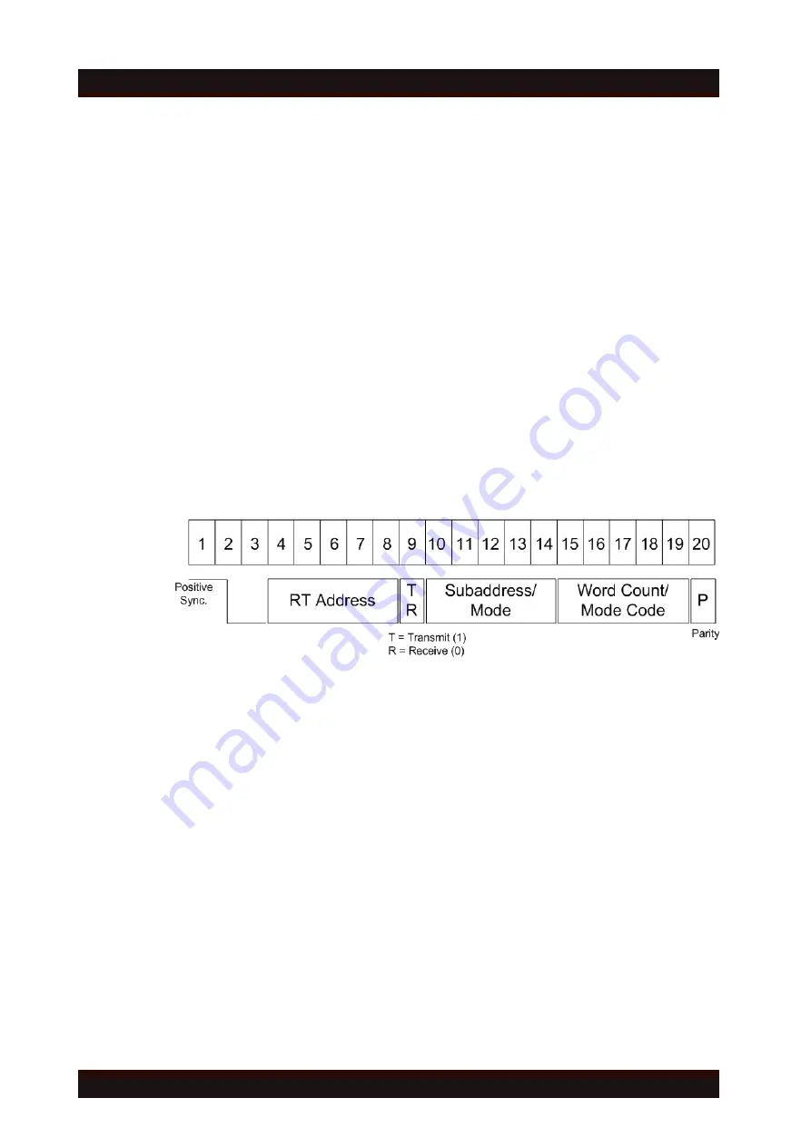
Command Word
Figure 12-41: Structure of a command word
The format of a command word consists of the following parts (see
●
Sync: an invalid Manchester waveform.
●
Remote Terminal (RT) Address: the unique address of the corresponding RT.
●
Transmit/Receive (T/R): indicates the action required from the RT.
●
Subaddress/Mode Code: indicates the RT subaddress. The subaddresses 0 and
31 signalize the transmission of a mode code.
●
Data Word Count /Mode Code: indicates the number of words that are sent/
received by the RT. A maximum of 32 words is allowed. This field may be used for
the transmission of the mode code value.
●
Parity: checks if there are bit errors during the transmission. The total number of
logic 1 bits for the word (sync bits not included) shall be odd.
MIL-STD-1553 (Option R&S
RTM-K6)
www.allice.de
Allice Messtechnik GmbH


