


HyperTrack™
Software Instruction
76
Quasonix, Inc.
0 degrees AZ and 0 degrees EL, and 2.0 is entered into the AZ and EL boxes. When the Go button is selected, the
antenna slews to +2.0 degrees Azimuth and + 2.0 degrees Elevation.
4.2.1.8.5.3 Velocity
The Velocity parameters command the AZ and EL axes at the velocity entered each axis field. In this example,
assume each parameter was set to 0.0. When the Go button is selected, the antenna does not move from its present
position.
If each parameter was set to 5.0, the antenna slews in both axes at a constant 5 degrees/second velocity. Negative
velocities command each axis to drive the antenna at the desired velocity, in the opposite direction. When
commanded, the Elevation axis slews at constant velocity until the axis reaches the Up or Down limits.
!CAUTION!
When using the Velocity parameters and commanding the EL axis to drive at a large velocity into
the Up or Down limits, the elevation axis components can be mechanically damaged. The Stop
Movement button, in the Misc. column, should ALWAYS be used to stop EL axis motion, NOT the
system limits.
4.2.1.8.5.4 Misc.
The Misc. column contains two buttons, Clear Faults and Stop Movement. When the antenna is commanded to drive
at a constant velocity, selecting the Stop Movement button stops all AZ and EL motion. This button should be used
to stop the Elevation Axis before it reaches the Up or Down limits, especially if a large velocity is entered into the
Velocity parameters.
4.2.2
Graphical User Interface (GUI), Front Panel Quick Open
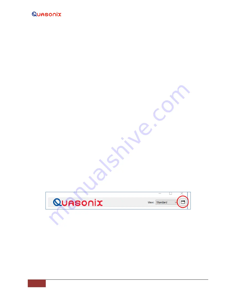
The Screen icon, shown in Figure 87, is used to quickly open multiple front panel/main screen displays. When the
Screen icon is selected, it instantly duplicates the front panel as many times as it is selected, as shown in Figure 88.
This enables monitoring of the front panel while simultaneously using other features and views described in this
manual. For example, the user can be monitoring the Front Panel and the Fault windows at the same time.
Figure 87: GUI Quick Open Icon


