


HyperTrack™
Software Instruction
96
Quasonix, Inc.
4.2.3.5
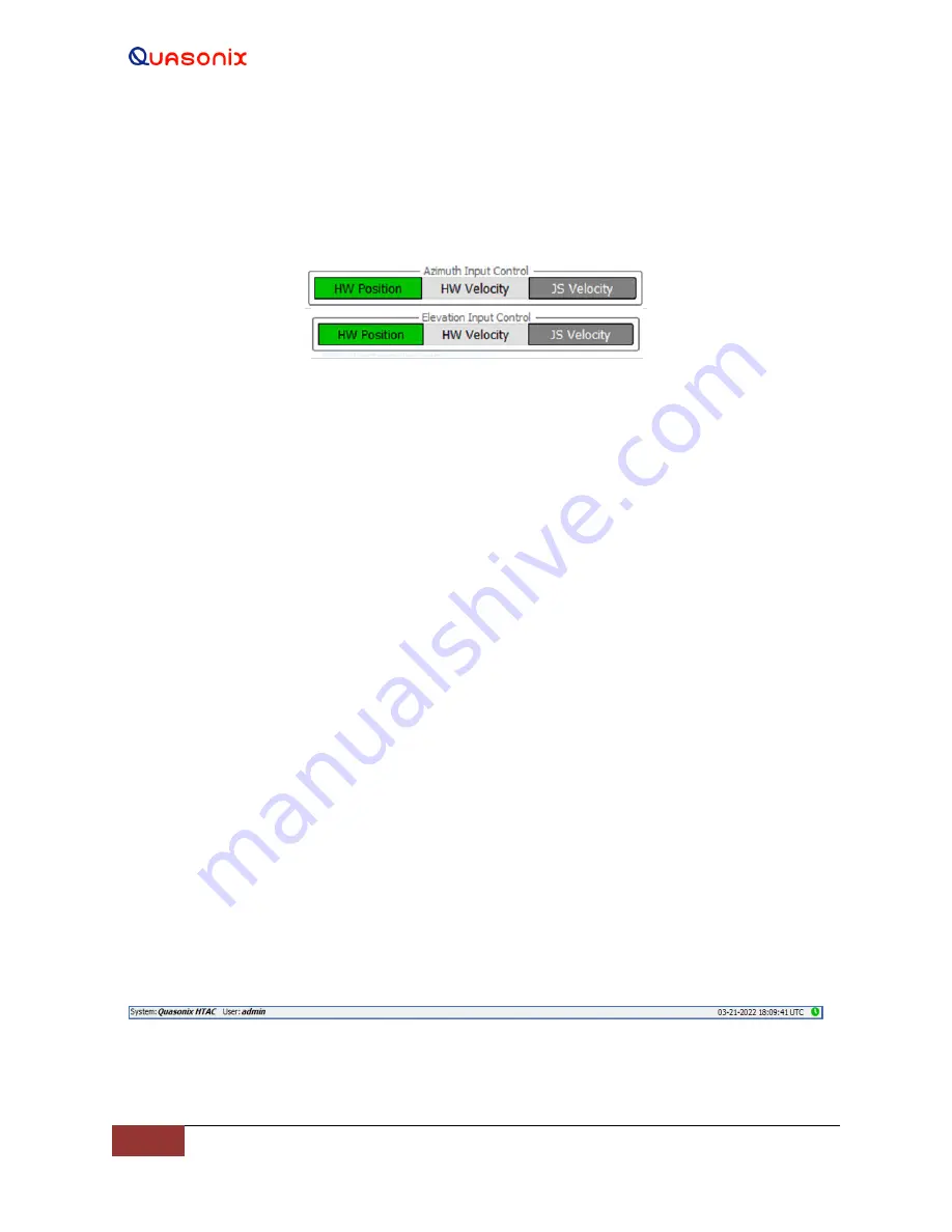
Azimuth and Elevation Input Control Windows
The Input Control windows, shown in Figure 118, allow the modes of manual antenna movement, either Position or
Velocity, for each axis independently. The Input Control windows are located at the lower left (Azimuth) and right
(Elevation) on the Main GUI screen.
Figure 118: Azimuth and Elevation Input Control Windows
Both inputs operate identically. The windows consist of three (3) buttons: HW (Handwheel) Position, HW
(Handwheel) Velocity, and JS (Joy Stick) Velocity. Before the handwheel and/or joystick can be used, the
Handwheel and Joystick settings windows must be configured and enabled for both devices (typically factory set).
4.2.3.5.1 HW (Handwheel) Position
This button selects the Handwheel Position mode, which drives the antenna CW and CCW or Up and Down as each
handwheel CW and CCW are rotated. When the rotation of the handwheel stops, the antenna also stops. This mode
is used to accurately drive or point the antenna to a desired location manually.
4.2.3.5.2 HW (Handwheel) Velocity
This button selects the Handwheel Velocity mode, which drives the antenna CW and CCW or Up and Down
continuously as the handwheel CW and CCW is moved. More rotational turns of the handwheel increases the
antenna speed up to its maximum AZ and EL speed limit (typically 30 degrees/sec). If the handwheel is released (no
longer turning), the antenna continues to move until the handwheel rotation is reversed. This slows down the angular
speed of the antenna until it stops. Continuing to rotate the handwheel in the reverse direction begins to drive the
antenna in the opposite direction, up to maximum velocity again. Driving the antenna in HW Velocity mode in the
Elevation axis eventually drives the EL axis into the system Up or Down limits.
4.2.3.5.3 JS (Joystick) Velocity
This button selects the joystick and places it in Velocity mode. If both axes are enabled, the joystick drives the
antenna in both Azimuth and Elevation, depending on the user input into the attached joystick. The joystick is
typically attached to the Client Windows PC via any available USB port. The Joystick settings window is then
accessed to select and enable the displayed joystick types.
4.2.3.6
Lower Tool Bar
The Lower Tool Bar contains two reference areas, as shown in Figure 119. The left side of the bar displays the
System connection information and the User login status. The right side of the bar contains the Time, Date, and Link
status.
Figure 119: Lower Tool Bar


