


HyperTrack™
Software Instruction
113
Quasonix, Inc.
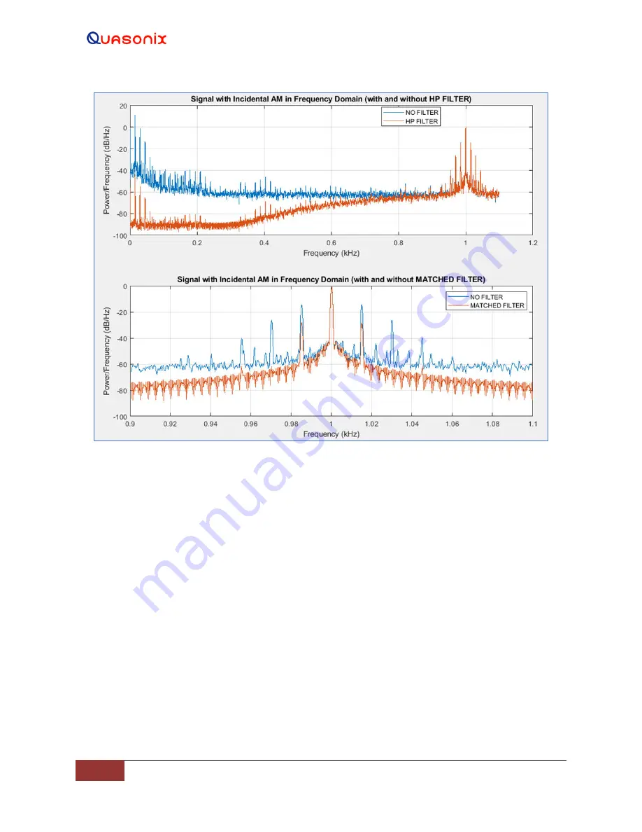
Figure 133: Rotor-rate Sidebands After HTAC Processing
8.4.5
Dynamic Tracking Loop Bandwidth Control
Every auto-tracking antenna is driven by a feedback loop. The AM imposed on the signal by the scanning feed is
used to steer the antenna toward the target. In the HyperTrack™ system, however, the bandwidth of this tracking
loop is automatically adjusted to provide an ideal balance between aggressive, high acceleration when needed, and
much smoother, more relaxed tracking when the test article motion is less dynamic. This all happens with no
intervention by the operator and the reduction in unnecessary tracking “jitter” is remarkable.
The tracking loop is continually estimating target statistics to determine the dynamics as well as the target noise.
Figure 134 illustrates how these estimates are used to create a loop bandwidth control surface that allows
HyperTrack
™
to handle a wide range of tracking situations automatically. When the target is moving fast and the
noise is low, the algorithm adapts by increasing the loop bandwidth. Similarly, if the tracking noise is high or the
target is moving slowly, the gain will be reduced. Generally, under low noise conditions, the loop is confident in the
tracking error estimates and the gain is increased. When the dynamics of the target increase, the trend is to increase
the gain to allow the system to keep up with the target. These actions exactly mimic how an operator would react to
the situation.
The shape of the surface is designed to provide good responsiveness and operational stability. This adaptive
approach to target tracking allows the system to cover a much wider range of conditions than traditional fixed gain
approaches and significantly reduces the amount of operator intervention required.


