


HyperTrack™
Software Instruction
17
Quasonix, Inc.
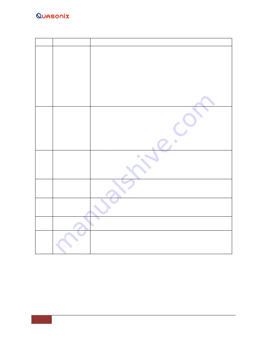
Item #
Window Name
Description
The A. Rx Threshold drop down menu provides the operator with a
choice of Auto Receiver gain selection points, where the tracking
channel switches from a lower to a higher received signal level at the
selected point. In Figure 12, the tracking channel switching level is set
to 3.0 dB. There must be a 3 dB difference between any tracking
channel, before a channel switch will take place.
The RSSI window also contains the L, S, and C Band (LNA)
amplification selection buttons. The selections are Hi, Md, and Lo
amplification for all available frequency bands. The gear buttons below
each tracking channel opens the track settings for that channel.
7
Mode Control
Elevation and Azimuth axes Mode Control window - Within this
section, the EL and AZ servos can be enabled and disabled; In
addition, the six (6) axis control modes of: Standby, Manual, Slave,
Search, Acquire, and Track are located here; When in AZ or EL
Manual Mode, this section contains the Camera Control button and the
gear buttons which open the multi-function Camera Control window;
the camera enable (ON-OFF) button and all of the other control
functions associated with the mode control are located there.
8
Designates or
Track
Multi-function display area - When a Gear button, next to any axis
mode button is selected, the settings, displays or parameter input
windows, associated with that mode button, are displayed; Designates
are located within this window and are accessed by selecting the gear
button next to the Manual button.
9
Elevation Input
Control
The Elevation Axis, Input Mode, Control buttons are located within this
narrow window; The Handwheel Position, Handwheel Velocity, and the
Joystick button, for control of the Elevation axis, display here.
10
Azimuth Input
Control
The Azimuth Axis, Input Mode, and Control buttons are located in this
narrow window; The Handwheel Position, Handwheel Velocity, and the
Joystick button, for control of the Azimuth axis, display here.
11
System
Lower Tool Bar - Contains the linked HTAC controller information and
the User login
12
Date/Time
Date and time information including the Time Input Link (small Clock
icon); The icon changes color depending on link status. Clicking on the
Clock icon opens the Time Synchronization status and sources
information page.
4.2 Graphical User Interface (GUI) Overview
The
HyperTrack™
GUI Main screen provides the operator command and status of the antenna tracking system. The
main display automatically opens after completing the Ethernet link to the
HyperTrack™
controller (HTAC). This
section describes the command and status functions available from the Main screen.


