20 BRIDGES
108 Planmeca Chairside CAD/CAM solution
User’s manual
The contacts of the bridge teeth will be fused together to
form the bridge, so the actual contact strength is not a
concern, but the contact should be heavy enough to
ensure a proper connection.
8. When you are satisfied with your designs, click the
Mill
tab.
20.6 Evaluating connectors
It is important to evaluate the connections on the bridge
and look for possible hangups.
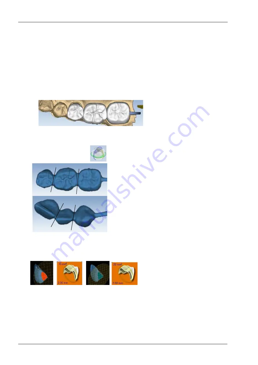
The sprue will be on the mesial or distal side of the bridge.
1. Click View Model to hide the model.
2. Click Sim.
When the Simulation is run, the connections between the
teeth are displayed.
3. Click Slice Plane twice.
When Slice Plane is activated on a bridge mill simulation,
the system measures the slice width. If the slice is thinner
than the material guidelines, the slice displays as red. It is
important to slice the simulation through the thinnest part
of the connectors (lines).
Posterior cases tend to have wider contacts with smaller
embrasures and are unlikely to be thin. Anterior cases
have smaller contacts and larger embrasures.
Any thin area should be evaluated.
4. Move the Slice Plane to a connector. If the Slice Plane
needs to be rotated to slice through the thinnest part, hold
down the Ctrl key while moving the mouse to rotate.
5. Rotate the model to view the slice.
6. If the slice is red, adjust the embrasures and/or contacts
and try the simulation again. Note that when the model is
hidden, the Slice Plane button displays the mm
2
area.
Minimum required thickness:
• Telio CAD - 12 mm
2
• IPS e.max - 16 mm
2
7. Click View Model to activate it.
8. Click the Gingival View Control arrow to view the model
from underneath.


