background image

19 MILL TAB


102 Planmeca Chairside CAD/CAM solution

User’s manual

19.3  Sending to mill

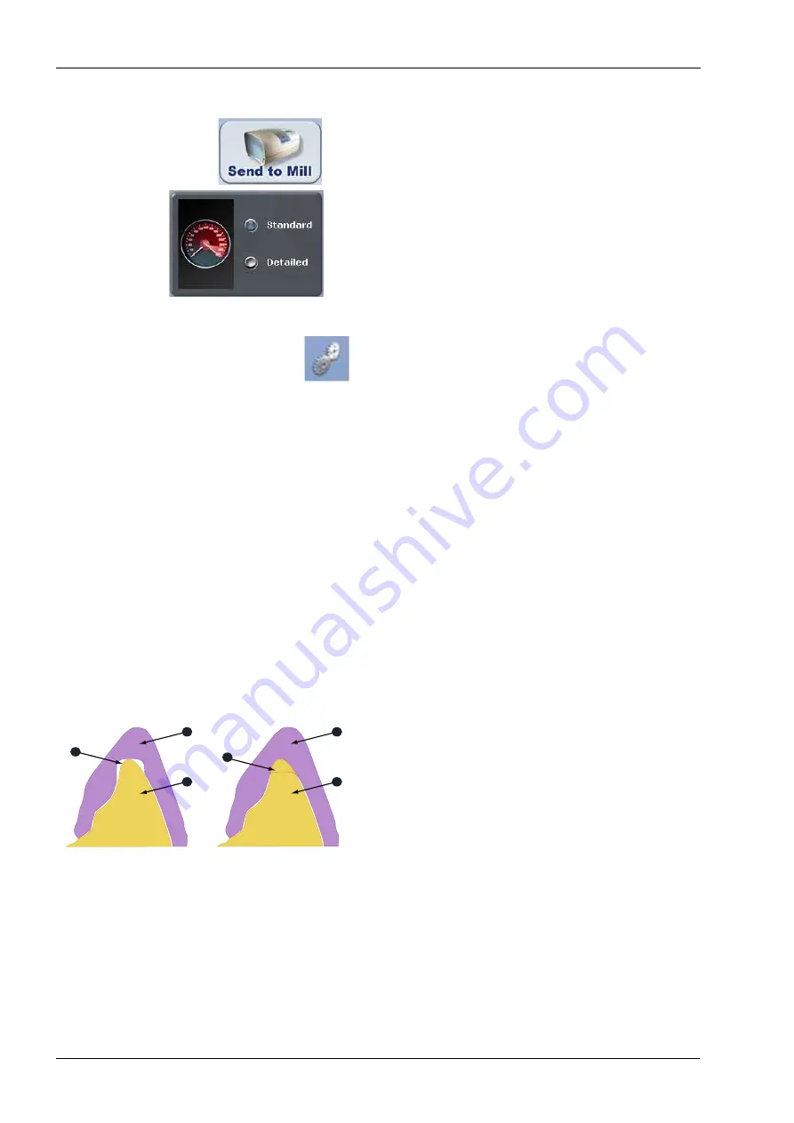
1. Click Send to Mill when you are satisfied with the 

restoration and mill set up.

2. Confirm the desired setting.
• Standard is recommended for full coverage restorations.
• Detailed is recommended for partial coverage 

restorations.

19.4  Mill tab settings

Click Settings to change any of the settings listed below.

19.4.1  Network settings

This should only be changed by a customer service 

representative. Incorrect network settings will make the 

Planmeca PlanCAD Easy unable to communicate with the 

job server and milling unit.

19.4.2  Material / shade settings

The material and shade for the current restoration can be 

changed here.

19.4.3  Margin thickness settings

Select the minimum material thickness along the margin. 

The recommended margin thickness is 70 to 100 microns 

to reduce margin chipping or potential short margins.

19.4.4  Milling settings

Milling Settings only affect proposals with a sharp interior 

angle, like an anterior incisal edge. If the interior of the 

proposal is smaller at the tip than the tools in the mill, the 

Standard setting removes extra material at the tip. This 

may lead to a crown that is too thin at the top. The options 

are to round the preparation or to select Undermill. If 

Undermill is selected, then the mill will go as far as the 

tool’s size will allow and the remainder must be removed 

manually.

1) Propo

sa

l

2) Prep

a

r

a

tion

s


3)

S

t

a

nd

a

rd

4) Undermill

1

2

3

1

4

3

Summary of Contents for Chairside PlanCAD Easy

Page 1: ...PlanmecaChairside CAD CAMsolution PlanmecaPlanScan PlanmecaPlanCAD Easy PlanmecaPlanMill 40 EN 10033946_6 user s manual...

Page 2: ......

Page 3: ...7 GETTING STARTED 17 7 1 Starting the software 17 7 2 Planmeca Romexis license activation 17 8 LOGGING IN TO PLANMECA ROMEXIS 19 9 MANAGING PATIENTS 20 9 1 General 20 9 2 Searching patients by name o...

Page 4: ...ultiple anteriors 64 15 17 Scanning impressions 64 16 ORIENTATION 67 16 1 Intraoral scanning examples 67 16 2 Viewing the model 68 16 3 Moving the central point 69 16 4 Single restorations 70 16 5 Ver...

Page 5: ...A 3D VOLUME 124 25 1 Opening a 3D volume 124 25 2 Importing intraoral scans to 3D volumes 124 26 SENDING AND RECEIVING CASES VIA PLANMECA ROMEXIS CLOUD 127 26 1 Planmeca Romexis Cloud user requiremen...

Page 6: ...ve the right to make changes without prior notice COPYRIGHT PLANMECA Publication number 10033946 Revision 6 Released 20 May 2015 Table of contents 29 CLEANING PREVENTIVE MAINTENANCE 146 29 1 Scanner t...

Page 7: ...orthopaedics or any indication beyond dentistry This manual is valid for Planmeca Romexis software revision 4 1 1 R or later The Planmeca Chairside CAD CAM solution requires Planmeca Romexis software...

Page 8: ...f dental restorations It is used for recording topographical characteristics of teeth dental impressions or stone models by digital methods for use in computer aided design and manufacturing of dental...

Page 9: ...ach can be found Be certain to read all product labelling NOTE If any of the labels are missing or illegible please contact Planmeca After Sales for replacement labels NOTE The labels may have changed...

Page 10: ...ower IEC 60417 5008 ON Power IEC 60417 5007 On Off Power IEC 60417 5010 Operating Instructions ISO 7000 1641 Serial number Standby IEC 60417 5010 Type B Applied Part IEC 60417 5840 UL Laboratory Equip...

Page 11: ...3 SYMBOLS ON PRODUCT LABELS User s manual Planmeca Chairside CAD CAM solution 5 3 1 Label locations 3 1 1 Scanner...

Page 12: ...3 SYMBOLS ON PRODUCT LABELS 6 Planmeca Chairside CAD CAM solution User s manual 3 1 2 Milling unit...

Page 13: ...external components to the Planmeca system attach only components that have been tested for compliance with IEC 60601 1 or UL 60950 Connectors for attaching external devices conduct low voltages Avoi...

Page 14: ...3 SYMBOLS ON PRODUCT LABELS 8 Planmeca Chairside CAD CAM solution User s manual UL listing UL Laboratory Equipment Listing IN ACCORDANCE WITH UL 61010 1 30SC...

Page 15: ...the Planmeca products for any purpose other than its intended and labelled use WARNING This is a Class A product In a domestic environment this product may cause radio interference in which case the u...

Page 16: ...used CAUTION Comply with all applicable regulations when dispos ing of waste materials from the Planmeca products 4 1 Planmeca PlanScan scanner Planmeca PlanCAD Easy WARNING The scanner s Thunderbolt...

Page 17: ...and placed into service according to the EMC information provided in the documentation that accompanies the Planmeca products CAUTION Portable and mobile RF Radio Frequency communi cations equipment...

Page 18: ...tter For products outside of the United States and Canada the power cord must be marked HAR or with a suitable agency marking from the country of intended use The attachment plug and appliance coupler...

Page 19: ...nd possible damage to the restoration block and cutting tools CAUTION Do not open the milling unit cover while a milling operation is in progress Doing so will result in the loss of data and restorati...

Page 20: ...ision 3 5 0 R or later 5 1 Software and hardware upgrades System software and hardware upgrades are initiated through Planmeca only No software or hardware should be added to or deleted from the Planm...

Page 21: ...s and Print Screen or Prt Scr keys The computer takes a screenshot and saves it in the folder Libraries Pictures Screenshots The screen shots are automatically numbered You can rename them if desired...

Page 22: ...The con nector pins on the scanner are energized when the tip is removed To ensure safety of the user and patient do not touch the pins when the tip is removed The tip can be removed by pressing the...

Page 23: ...can vary 7 2 1 Automatic online activation A dialogue requesting for activation will pop up when Planmeca Romexis Client is started until activated after new and updated Planmeca Romexis server insta...

Page 24: ...anual 7 2 3 Transferring license to another installation If transferring the license from one Planmeca Romexis server installation to another it must be first released from the current workstation To...

Page 25: ...Patient module The name of the current user is shown in the title bar To login as different user click this button To logout click this button All currently opened files will be closed NOTE If you ar...

Page 26: ...ull dialogue view opens 9 1 2 Sorting patients Patients in the patient list can be sorted by date ID or name by clicking these buttons 9 2 Searching patients by name or ID Start entering the name or t...

Page 27: ...ent data see section Reactivate and empty trash in the Planmeca Romexis technical manual 10037884 9 4 Managing patients and images 1 Click the patient on the list If the access reason for accessing th...

Page 28: ...and modify the desired information 3 Click the Save Patient button 9 4 2 Adding patients 1 To create a new patient click the Add patient button 2 Enter the necessary information and add a photo if des...

Page 29: ...nts Click the Add template button Virtual patients 1 Select the template patient from the patient list 2 Click the Add virtual button The name of the student can be included in the name e g Jane s Chi...

Page 30: ...cheduled imaging modality or date range When selected a patient is automatically added to the Planmeca Romexis database if not already registered If a near match exists in the database the user will b...

Page 31: ...he Study button in the expanded view 9 7 Searching patients by image Patients can be searched by image comment or diagnosis image type and date Enter or select the desired search term and click Find T...

Page 32: ...ation All data are automatically stored into Planmeca Romexis database and organized into cases to be exported to another system or sent to a certified laboratory for design and milling using Planmeca...

Page 33: ...10 5 Import 3D models Click 3D model import The following window opens You can import models either from an external source A or from Planmeca Romexis 3D module s Volumes tab B To import models from a...

Page 34: ...3D models 10 7 1 3D Model Export To export models as STL files select them from the list and click 3D model export 10 7 2 Cloud Export To export case files to Planmeca Romexis Cloud select them from...

Page 35: ...only The case opens in Planmeca PlanScan scanner s Scan tab 10 8 3 Viewing STL files in 3D module Right click on the case and select View STL in 3D Module By clicking this icon on the top right corne...

Page 36: ...nual 10037884 1 Open the image you want to store 2 Click the DICOM storage button 3 Click OK in the opening dialogue To check the status of storage transaction use the Image Properties dialogue DICOM...

Page 37: ...he in the 3D module volumes list To open a scan restoration for viewing and further processing double click on it To view the properties of a scan restoration see section 22 2 1 Image properties on pa...

Page 38: ...al type and shade You can select between FDI ISO two digit FDI World Dental Notation and Universal Numbering System adopted by the ADA American Dental Association The numbering system can be set in Pl...

Page 39: ...ct the type of restoration by clicking on the appropriate restoration type on the left crown inlay onlay veneer or pontic 3 Select the opposing scan type NOTE The majority of Planmeca Romexis Cloud re...

Page 40: ...he Design tab The system offers block size options on the Mill tab The material can be changed on the Mill tab settings 7 If setting up a bridge select all the teeth you want to use for the bridge by...

Page 41: ...7 1 2 through 10 2 2 are Anterior A2 Teeth 6 1 3 and 11 2 3 are from Library A Cutback A4 For further processing in dental laboratories The lingual pictures below show the anterior library options gr...

Page 42: ...lour and strength when fired In its final tooth coloured state IPS e max CAD offers 360 MPa of flexural strength which is nearly three times the strength of many millable ceramics available chair side...

Page 43: ...estoration Anterior Full crown Anterior Veneer Posterior Full crown Inlay Onlay Implant Bridges Material 3M Lava Ultimate Ivoclar Vivadent IPS Empress CAD HT IPS Empress CAD LT IPS Empress CAD Multi I...

Page 44: ...nCAD Easy cart Properly connecting and disconnecting the scanner will prevent damage to your devices 1 Attach the connector of the scanner into the adapter as illustrated 2 Make sure the end is fully...

Page 45: ...scanner along the mesial distal axis with the tip of the scanner pointing towards the distal The axis follows the curve of the arch The pictures show correct and incorrect positions along the arch 2...

Page 46: ...mation see your dental unit s User s manual 2 Scanner tip total usage time counter 3 Accuracy optimization slider 4 Model editing tools 5 View editing tools 6 Alignment tools 7 View modes 15 1 1 Scann...

Page 47: ...current model Restore data Use this tool to restore all data erased after scanning 15 1 4 View editing tools Impression model view Click this button to change between the impression model view and no...

Page 48: ...g the prepared site of the restoration All free flowing blood saliva and residue should be removed from the preparation site before scanning Opposing For scanning the teeth on the opposite arch of the...

Page 49: ...aluate the model and make adjustments as needed 10 Select the next scan type 11 Repeat the steps above 12 When finished with scanning click the Margin tab or click the Next button The green colour ind...

Page 50: ...e screen To adjust the size of the FOV field of view see section 15 4 2 Adjust the scanning field of view on page 49 The opposing scan looks like this 15 If necessary remove the extra material from th...

Page 51: ...er on page 39 The live image shows on the screen The buccal and opposing teeth will be automatically aligned The successful alignment is indicated with the green point on the top right corner of the a...

Page 52: ...is automatically saved to Planmeca Romexis 15 3 Scanning a basic posterior preparation Goals 100 of the prep and interprox contact areas 90 of the adjacent teeth Good axial data buccal and lingual fo...

Page 53: ...why you always want to rotate to the right before going to the left 1 Use small rotations over the mesial proximal neighbour to create overlapping scans as you transition from occlusal scans to a cloc...

Page 54: ...w to orange The most recent scan added to the model is displayed with a colour coding to indicate the focal distance of the data added Green close to the tip Yellow Orange middle of the range Red end...

Page 55: ...dow To make it smaller place the mouse cursor on the left edge of the Live View Right click and drag the window to the desired size The Live View will return to the default size next time it is activa...

Page 56: ...n Ensure there is enough detail approximately 90 to align the restoration with its neighbours 2 If not already activated click Data density view The model refreshes with the dark blue and purple areas...

Page 57: ...an be used to remove unnecessary data like extra teeth tongue cheek etc It can also be used to erase an area that needs to be rescanned If you spot a problem i e the margin is partially hidden by cord...

Page 58: ...u will use the Time Saver method You always have the option of simply doing a full scan for each model type 15 8 Scanning a bite registration A bite registration can be used to optimize occlusion for...

Page 59: ...3 Click Bite A Time Saver message appears It only appears when the preparation is scanned first The time saver option allows you to duplicate the preparation model and use the same data for the bite...

Page 60: ...tration material and any of the adjacent tooth data that was removed and is not covered by the bite registration 15 9 Selecting bite registration Highlight the opposing dentition to designate which ar...

Page 61: ...h an occlusal view scan the occlusal surfaces of the opposing dentition Include the same number of teeth as the preparation model Ensure there is good cusp tip data on both the lingual and buccal side...

Page 62: ...ip against the cheek and not rubbing against the gingiva during scanning is typically more comfortable for the patient 4 Place the scanner at a 90 angle to the teeth 5 Scan the sides of the teeth that...

Page 63: ...are generated A green dot means the scans are aligned A red dot means they are not aligned To view the alignment click the icon All of the alignment icons have a Refresh button To reset the alignment...

Page 64: ...eactivate the selected Alignment icon You cannot proceed if the Alignment icon is active orange 15 12 1 Aligning buccal data The buccal bite should automatically align When the alignment is successful...

Page 65: ...feature on both models 3 Click directly on a distinctive feature in the buccal bite and drag the model until the pointer is directly over the same distinctive feature on the preparation model As you...

Page 66: ...model snaps into place Your alignment should resemble the following If the system is unable to align the drag and drop points that you selected the models will go back to their original positions Try...

Page 67: ...ion model NOTE Time Saver cannot be used in conjunction with Impression Mode 4 Click OK to use the Time Saver If you do not wish to use the Time Saver option the preparation and adjacent teeth can be...

Page 68: ...mpass the extra preparation s 1 Select the tooth number for the first preparation and then select a preparation type material and shade 2 Click the Scan tab 3 Repeat for each prepared tooth 4 Start on...

Page 69: ...t area Anterior teeth are often very similar to each other Following the suggested scanning steps lowers the chances of misalignment The scanning method is the same for all anteriors When scanning int...

Page 70: ...osition If the second scan aligns correctly continue scanning in the normal pattern When crossing the mid line lingual scans are recommended for more data and fewer flat surfaces After you turn the sc...

Page 71: ...scanner may not be able to capture all of the walls of the impression You can also tilt the scanner up or down to achieve the necessary point of view 15 17 2 Scanning See section 14 4 Positioning the...

Page 72: ...additional scans such as the mesial interproximal area shown above take extra scans 5 Click Data Density View to deactivate it 6 Click Impression Mode to invert the model into the normal view All oth...

Page 73: ...ns when greater adjustments to Orientation are required 16 1 Intraoral scanning examples Tooth position and size of the patient s mouth can sometimes make it difficult to get a perfectly positioned fi...

Page 74: ...left mouse button 16 2 Viewing the model In Orientation the model displays with a circular graphic labelling the mesial distal buccal and lingual surfaces Zoom out to see the buccal and lingual label...

Page 75: ...on the preparation but it can be helpful if you are new to rotating a 3D model or if you have multiple preparations The example below shows a preparation with no distal neighbour so the prep is not in...

Page 76: ...the model until it has a good buccal lingual alignment You should be able to see the occlusal tables clearly and the same amount of data on the buccal and lingual sides of the adjacent teeth The centr...

Page 77: ...ation from the buccal or lingual point of view because it is easy to accidentally change the mesial distal alignment at the same time 4 Click Occlusal 5 From the occlusal ensure the model is straight...

Page 78: ...of the model 2 From the occlusal check that the central groove is in alignment 3 From the buccal check that the marginal ridges are parallel to the marginal ridges of the adjacent dentition NOTE The...

Page 79: ...times to turn the model around 3 Continue with the normal Orientation work flow 16 8 Multiple restorations A different Orientation is assigned to each restoration The curve of spee affects the orient...

Page 80: ...n for each restoration 1 Click and hold down the scroll wheel 2 Drag the model until the first tooth is centred in the middle of the screen The circle moves with the model but you can see the model mo...

Page 81: ...h for that tooth 6 While on the second tab click Orientation to designate the orientation for the second preparation 7 Drag the model so that the second preparation is centred 8 Rotate the model to th...

Page 82: ...e view on the Margin tab which will be called here as Margin view tools 17 1 Margin tool set You can use the following tools to draw and adjust the margin Paint Create the margin using a broad brush s...

Page 83: ...To delete the margin and start over click Paint Trace or Lasso button Trace tool The Trace tool can be used on any margin but it is especially recommended for equigingival and subgingival margins 1 C...

Page 84: ...f continuous lines 6 Finish the margin by clicking on the starting point The system automatically changes the trace line into a margin line 7 To delete the margin and start over click the Trace or Las...

Page 85: ...gments The system redraws the margin and removes the unacceptable section Repeat as needed 17 1 2 Move margin tool Use the Move Margin tool to drag and drop a section of the margin into a new position...

Page 86: ...g a circle around the entire tooth After you let go an area is highlighted Do not go too far beyond or short of the natural tooth or the proposal will be distorted This process is recommended for inla...

Page 87: ...bottom of the screen These act the same as the margin tools Trace Removes the existing line Draw a new pre op area Move Curve Click to drag an exiting curve into a new position Add Segments Click to a...

Page 88: ...7 4 Margin aids View ICE Preparation NOTE For intraoral cases only Use View ICE Preparation to toggle between ICE view and stone view Show Features The Show Features tool can be used to highlight high...

Page 89: ...rgin must be marked again on the correct tooth tab NOTE See section 20 BRIDGES on page 104 on how to draw pontic margins 17 5 Margin tab settings 17 5 1 ICE margin mode NOTE For intraoral cases only I...

Page 90: ...ned the margin the Design tab provides an array of tools and options to customize the proposal Select from the design tools on the left menu each of which provides additional options in the box below...

Page 91: ...appear in the Options box below the restoration A green preview tooth display The selected library is highlighted in yellow 18 1 1 Select a library If desired click another library to view the previe...

Page 92: ...as library tooth When Pre op is selected as the Library tooth Autogenesis combines the pre op selection with the Library A tooth Use the following steps to move or resize the library A tooth to modif...

Page 93: ...f desired return to the Margin tab and edit the Selection Area Material thickness To show hide the material thickness indicators in the Design tab click Material Thickness When Material Thickness mode...

Page 94: ...click View Contacts To hide the adjacent dentition from view select Hide Model When View Contacts is active the system colours the proposal based upon contact strength at each point on the restoration...

Page 95: ...yellow or bite registration opposing model blue template appears on top of the restoration To make the template translucent click View Pre op or View Bite Registration again Use the slider to adjust...

Page 96: ...a numerical distance field in conjunction with six directional arrows to move the occlusal table 1 Use the number field or pop up list to set the movement distance in microns 2 Click the desired dire...

Page 97: ...ool to change the form of the restoration by pushing or pulling inward or outward on the restoration In this example the tooth was pulled in the direction of the arrow 1 Click the Rubber Tooth tool 2...

Page 98: ...ture Small moves are recommended Rotate and zoom as needed to view the changes 4 To discard changes click Undo 18 4 4 Smooth surface Use the Smooth Surface tool to make an area of the proposal s surfa...

Page 99: ...ired position or shape 18 5 Contact refinement Contact Refinement enables you to set the strength of the occlusal and or interproximal contacts It also enables you to broaden the interproximal contact...

Page 100: ...e axial and occlusal walls Margin ramp is the contact zone for the margin Use the sliders or pop up menus to change the values 18 7 Design tab settings Click Settings to select which features Autogene...

Page 101: ...ration type 18 7 2 Contact strengths Contact Strengths designates the default strength of the Proximal Contact and Occlusal Contact in Autogenesis and Contact Refinement NOTE Autogenesis may not creat...

Page 102: ...y the vertical arrow 0 150 in the example The vertical slider on the right is the height of the material added This is generally kept towards the bottom near the margin The effects of this tool are mo...

Page 103: ...e same time or activates all proposals at the same time to enable individual manipulation without switching tooth tabs To manipulate all proposals at the same time use Incremental Change Tools Move Ro...

Page 104: ...ng process at the milling unit load the block ensure the milling tools are in place and verify the fluid is at the correct level 19 1 Setting up restoration for milling The final restoration setup is...

Page 105: ...between lingual and the mesial or distal Premolars mesial or distal Inlays and Onlays largest proximal box NOTE The sprue connects the restoration and the mandrel To ensure the sprue is not positioned...

Page 106: ...restoration It takes about 10 seconds to generate and is recommended before milling to check the internal fit If a hang up is seen you can increase the spacer or make any other necessary design change...

Page 107: ...or overmilling yellow with only a slight increase in the spacer and on a different slice of the same proposal there is an overlap which would cause a hangup red Analyzing and fixing these issues requi...

Page 108: ...gs The material and shade for the current restoration can be changed here 19 4 3 Margin thickness settings Select the minimum material thickness along the margin The recommended margin thickness is 70...

Page 109: ...ion Settings The default selection is Speed This will give you a faster simulation Select Quality for a more accurate simulation but be aware that it will take longer to process Note that when the sof...

Page 110: ...reparations for the abutment teeth are not angled in different directions If one is pointed towards the lingual and the other towards the buccal there may be problems with path of insertion and over m...

Page 111: ...e The software will replace the Material and Shade of the remaining restorations with that of the highest tooth number after the link Multiple bridges can be created on the same arch Repeat the steps...

Page 112: ...bridge 1 Click the tooth number tab for each abutment and draw the margin on the selected tooth An edentulous space does not technically have a margin The margin is drawn to aid the design process 2...

Page 113: ...sal The size and position of the preview tooth is important when autogenesis is deactivated 2 Resize Alt arrows and move drag and drop as needed 3 Click Apply 4 Repeat these steps for the other abutme...

Page 114: ...es the slice width If the slice is thinner than the material guidelines the slice displays as red It is important to slice the simulation through the thinnest part of the connectors lines Posterior ca...

Page 115: ...idges The default Spacer Tool settings are different on bridges to account for the larger Path of Insertion The normal maximum for the spacer is 0 20 mm On bridge cases the spacer defaults to 0 20 mm...

Page 116: ...an scroll to left and right between the settings categories by placing the mouse cursor over the arrow To select the settings you would like to modify clicking on the category button To restore factor...

Page 117: ...f restoration When selecting Optimized the placement is based on the fastest milling time In all cases the sprue can be manually moved on the Mill tab 21 4 Margin ramp For design systems Default 0 25...

Page 118: ...vate the Spaceball option 21 8 Network settings This screen should be used only under supervision of a customer service representative These settings are pre configured and should not be changed 21 9...

Page 119: ...In Milling Settings you can select Standard overmill or Undermill setting This settings only affect proposal with a sharp interior like an anterior incision edge If the interior of the proposal is sm...

Page 120: ...ng the Settings button on the top right corner of the window To select the settings of a specific category click on the button These screens contain preference settings that modify the default behavio...

Page 121: ...e click on a case on the list or click the Open Restoration button The case opens in the Setup tab of the Planmeca PlanScan scanner To open a case in 3D module right click on the case and select View...

Page 122: ...Planmeca Romexis 3D module All scans and designed restorations will automatically appear in the 3D module s Volumes view 22 2 1 Image properties Right click on a scan restoration in the Volumes tab an...

Page 123: ...ct or enter the search criteria 3 Select the patient and click OK 22 3 Inactivate Right click on a volume in the Volumes tab and select Inactivate see the image above To remove the scan from the list...

Page 124: ...rom an external source A or from Planmeca Romexis 3D module s Volumes tab B To import models from an external source A 1 Click Browse 2 Go to the folder from where you want to import the models 3 Sele...

Page 125: ...nual Planmeca Chairside CAD CAM solution 119 To import models from the Planmeca Romexis 3D module s Volumes list B 1 Click Select 2 Select the file to import and click OK The imported files will open...

Page 126: ...and it has integrated 2D and 3D image viewer with 3D surface rendering Images acquired using Planmeca Romexis desktop software can be accessed on the local network Planmeca iRomexis is compatible wit...

Page 127: ...f you have multiple servers configured you can set the respective Planmeca Romexis server as default It is possible to add multiple Planmeca Romexis server connections to the server list 3 To test the...

Page 128: ...n the Planmeca iRomexis main window Viewing Images stored in the iRomexis In the Patients view click on the Local tab to see the patients stored in Planmeca iRomexis database Viewing Images Stored in...

Page 129: ...tore a snapshot of the current image to the Camera Roll of the iPhone iPad click on the camera button To reset the image to its original state click on the Reset View button To make distance measureme...

Page 130: ...o 3D volumes 1 Open the 3D volume you want to match with the surface model 2 Start matching by clicking the IO Scan Import button To match a new surface file select Browse To match an existing surface...

Page 131: ...an select landmarks on any side of the anatomy To undo and repeat the previous step click the Back Repeat button Ideally the landmarks should be placed on corners of occlusal and buccal or distal and...

Page 132: ...nual Additionally the following options can be selected Allow Scaling When enabled Planmeca Romexis will stretch the surface model to achieve better fit with the CBCT volume Note that this may alter p...

Page 133: ...ject to change For latest information see Planmeca Online website Planmeca Romexis Cloud subscribers Casual user Planmeca Online account holder Planmeca Romexis Cloud subscriber Internet access and e...

Page 134: ...time your private keys will be created in the Planmeca Romexis database To access the cloud from another computer you need to move your private key to that computer using the Export Keys and Import Ke...

Page 135: ...click Download The download progress is shown in the Cloud Management field Once the download is completed the case can be opened Open the case by selecting it and clicking Open The cases can be opene...

Page 136: ...ion User s manual 27 CONFIGURATION APPLICATION 1 From the Windows Start menu select All programs Planmeca Romexis Configuration 2 Log in to the Planmeca Romexis Configuration application by entering y...

Page 137: ...exis Configuration application under General Settings Cloud Servers as follows Configure the Cloud server as follows Cloud Server Address eu online planmeca com Port 443 In cases where Planmeca Romexi...

Page 138: ...and devices select the suitable alternative from the drop down menu To reactivate patients images or devices select the appropriate alternative from the list and click the Reactivate button The select...

Page 139: ...27 CONFIGURATION APPLICATION User s manual Planmeca Chairside CAD CAM solution 133 27 3 Class server In order to test the server connection the Class Server Enabled option must be selected...

Page 140: ...een To turn off the milling unit touch Maintenance to see the Mill Options screen 1 Touch Turn off the mill 2 Touch Select A confirmation screen appears 3 Touch Yes to turn off the mill Touch No to le...

Page 141: ...reservoir 3 Empty the fluid reservoir according to your approved material disposal protocols 4 Turn OFF the mill 5 Disconnect all power and data connections 6 Lift the mill onto a cart that is capabl...

Page 142: ...If turning is required turn by shuffling your feet not by twisting their body 13 If it is necessary to place the mill below the level of the waist Each person lifting should follow these procedures in...

Page 143: ...ct Identification Labels affixed to the rear of each unit see section 3 SYMBOLS ON PRODUCT LABELS on page 3 28 6 Job server The job server can be left on overnight but it should be shut down and resta...

Page 144: ...l NOTE The mandrel is the metal piece of the restoration block that is inserted into the mill to hold the block steady during milling 28 8 1 Horizontal orientation For the horizontal orientation the w...

Page 145: ...ming solution A composite block de foaming solution is used with 3M s Paradigm MZ100 blocks Due to the nature of the composite material when milled it is necessary to use this solution every time you...

Page 146: ...lling process is complete the lid automatically opens 2 Remove the restoration and any debris and close the lid 28 11 Parked job When a job is interrupted by an error message or a manual cancellation...

Page 147: ...finished jobs This does not affect the patient or restoration lists in the Planmeca PlanCAD Easy 1 Touch the Maintenance button The Mill Options screen appears 2 Touch Delete job list The job list is...

Page 148: ...ool breaks halfway instead of at the shoulder the broken tool may not be detected right away If the broken tool continues to mill it can cause damage or put black marks on the restoration By default t...

Page 149: ...ppears In the example below there is a tool in each spindle three extras in the tool changer and one empty slot green outline There are two vacant places shown in the tool changer that do not have the...

Page 150: ...from the Planmeca PlanCAD Easy The Mill Status button appears in the upper right corner on all Planmeca PlanCAD Easy screens The button is inactive on the Scan tab 1 Click Mill Status to see the Job L...

Page 151: ...ystem has been put into Override Mode by Customer Support or a service technician the following screen will be displayed upon startup The Override warning button appears on all screens Touch the butto...

Page 152: ...Cleaning Use a disinfectant wipe to remove any visible debris on the scanner tip and or rinse the tip for 2 minutes under running tap water to remove the rest of the debris After cleaning continue wit...

Page 153: ...cording to the standard EN13060 NOTE Autoclave cycle names differ among manufacturers Reference your manufacturer s manual to select the cycle for sterilizing wrapped instruments 5 Autoclave the pouch...

Page 154: ...ensure proper operation of the mill WARNING Operating the milling unit with insufficient milling fluid will damage the mill void your warranty and destroy the restoration that is being milled Personal...

Page 155: ...rt of water If additional fluid is required then perform a tank cleaning and replenish the tank with fresh coolant and water 6 Replace the tank in the drawer 7 Close drawer carefully with audible clic...

Page 156: ...e cap and remove the spindle cap and gasket Ensure the gasket has been removed along with the spindle cap Sometimes it sticks to the spindle housing 4 Remove the collet using the other side of the col...

Page 157: ...ut motion and do NOT use a circular motion NOTE The air must be blowing during this step 9 Use a dental mirror to inspect the spindle or rotate it using the wrench to ensure all the debris has been re...

Page 158: ...spindle cap at an angle This will push any ceramic build up out of the hole 14 Clean the cap and the gasket with water 15 Replace the spindle cap with the gasket 16 Align the spindle cap and gasket u...

Page 159: ...y placed in the tool changer and the bellows are moved out of the way The lid pops open when ready 3 Use the Spindle Cap Tool to turn the spindle cap counter clockwise until the point of the spindle i...

Page 160: ...are from the slits in the collet If they are not cleaned the collet will not seat properly and will lead to walking tools NOTE The lines are not necessarily going to be positioned as seen in the exam...

Page 161: ...and use the collet tool to tighten the collet Be sure to use your fingertips to turn the tool to avoid using too much torque 13 Insert the Nozzle Cleaning Brush in the small holes on the spindle cap...

Page 162: ...e when selected 4 Touch Unlock Drawer You will hear the water purge The text on the button changes to Lock Drawer 5 Pull the tank drawer open 6 Touch Lock Drawer The float stainer assembly lowers down...

Page 163: ...13 Fill the tank with 1 gallon and 6 ounces of coolant Reinstall the wire basket and tank lid Place the tank assembly in the drawer 14 Look under the mill and ensure that the float strainer assembly...

Page 164: ...canner with tip 48 x 53 x 276 mm 1 9 x 2 1 x 10 9 inches Scanner without tip 48 mm x 53 mm x 188 mm 1 9 x 2 1 x 7 4 inches Scanner tip 40 5 x 49 x 123 mm 1 6 x 1 9 x 4 8 inches Weight Scanner with tip...

Page 165: ...PlanScan is for indoor use only The user moves the sensor into the operation position by hand The system is used by dental care professionals Prior to installation of the system check that the local c...

Page 166: ...dical Electric Equipment EN 60601 1 2 Electromagnetic Compatibility EN 60825 1 Safety of Laser Products EN ISO 14971 2012 Risk Management EN ISO 13485 Quality Management Systems EN ISO 10993 Biologica...

Page 167: ...on NOTE This equipment has been tested and found to comply with the limits for a Class A digital device pursuant to part 15 of the FCC Rules These limits are designed to provide reasonable protection...

Page 168: ...eatures that prevent exposure to any hazardous levels of laser radiation in normal operation modes and in any reasonable fault conditions 30 4 External components and connectors When connecting extern...

Page 169: ...um Acting or T 1500A Breaking Capacity Air requirements 50 130 psi minimum 2 cfm filtered dry air Data connection requirements Cat5 Ethernet cabling Storage conditions 29 C to 38 C 20 F to 100 F Opera...

Page 170: ...standards ISO EN 14971 EN ISO 13485 2003 AC 2009 ISO 13485 2003 CFR 21 Part 820 SOR 98 282 Canada Medical Device Regulations FDA Class II Special Controls for Computer Assisted Design and Manufacturi...

Page 171: ...to cause any interference in nearby electronic equipment RF emissions CISPR 11 Class A The Planmeca PlanScan scanner is suitable for use in all establishments other than domestic and those directly c...

Page 172: ...nded that the Planmeca PlanScan scanner be powered from an uninterruptible power supply UPS or a battery Power frequency 50 60Hz Magnetic field IEC 61000 4 8 3 0 A m 3 0 A m Power frequency magnetic f...

Page 173: ...d FM radio broadcast and TV broadcast cannot be predicted theoretically with accuracy To assess the electromagnetic environment due to fixed RF transmitters an electromagnetic site survey should be co...

Page 174: ...s rated at a maximum output power not listed above the recommended separation distance d in meters m can be estimated using the equation applicable to the frequency of the transmitter where P is the m...

Page 175: ...switch at rear of the unit to ON position Failing to send restoration See job server troubleshooting Fan making loud noises Out of balance Replace fan Call Customer Support Software application freezi...

Page 176: ...ly Faulty sensors Fill tank with water Clean or replace sensors Call Customer Support Tool stuck in collet Collet rusty or caked with ceramics Tool jammed due to air pressure Remove tools manually Don...

Page 177: ...on to Multi Block but be sure to select the same block size You can then insert a standard Empress LT or HT block of the same size The milling unit makes multiple passes on Multi blocks while other ma...

Page 178: ...ls such as oil and heavy metals must be disposed of in accordance with local and national waste legislation and instructions issued by the environmental authorities The risks involved and the necessar...

Page 179: ......

Page 180: ...Planmeca Oy Asentajankatu 6 00880 Helsinki Finland tel 358 20 7795 500 fax 358 20 7795 555 sales planmeca com www planmeca com...

Reviews: