


PACIO MODULES
116
Parker Automation Controller Installation Guide
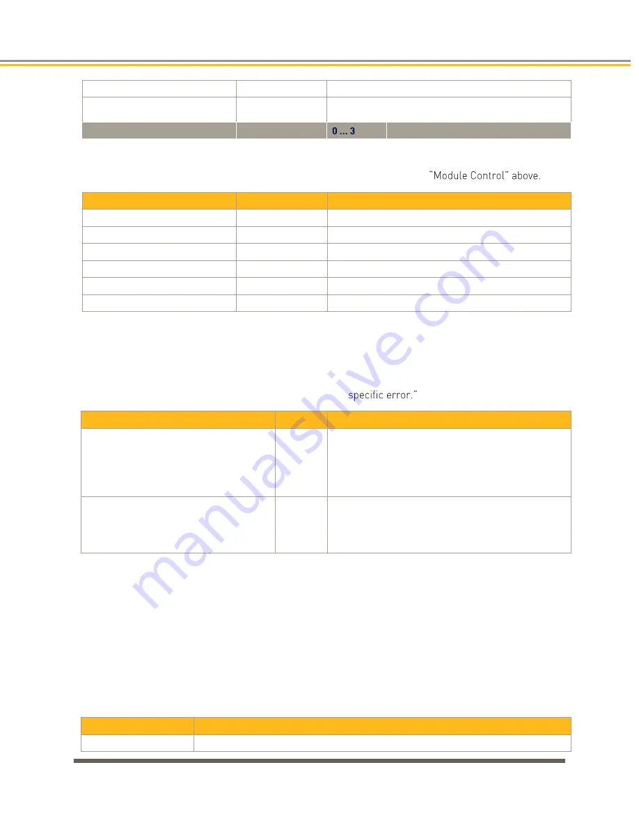
Channel_n_ResMode
BOOL
Set channel n to resistance mode
Channel_n_Filter
USINT
Set filter for channel n.
The arithmetic mean is output after n+1 conversions
n
Channel number
Module State
The following Module states are indicated below. To reset the messages, see
Variable
Data type
Explanation
Shortcut
BOOL
not used
Undervoltage
BOOL
not used
Watchdog
BOOL
Internal watchdog of Module
EtherCAT_Error
BOOL
Configuration error or watchdog control
Specific_Error
BOOL
Module-specific fault
OptionsSet
BOOL
Sent by Module to acknowledge SetOptions
Module-Specific Messages
Apart from the Module error messages, the set of messages below contains details about the current
state of the PACIO AI4-Pt/Ni100 16 Bit and PACIO AI4-Pt/Ni1000 16 Bit Modules. These messages are
automatically reset when the state concerned has returned to normal. They are combined into a single
"Specific_Error" state and output to the IO LED as "Module-
Variable
Data type Explanation
Channel_n_Open
BOOL
- Channel n load is gt minimum
- Broken wire of connector 0 *
- Broken wire of connector 3 *
- Broken wire of connector 0/3 *
Specific_Error = TRUE
Channel_n_Shortcut
BOOL
- Channel n load is lt minimum
- Short circuit of connector 0-3 *
- Broken wire of connector 2 *
Specific_Error = TRUE
*The causes of 'short circuit' and 'broken wire 0.3' are shown for channel 0 (equivalent applies to other
channels).
Conversion Time
The analog signals are converted one by one down every channel. Disabling one or several channels will
shorten the entire analog-to-digital conversion cycle.
'Filter' in this case means to compute an average when the set filter time is over.
Analog value conversion runs cyclically and is not synchronized with the receipt of EtherCAT telegrams.
The cycle consists of the analog value conversion plus transmitting the values into the EtherCAT data area.
Number of Channels
Cycle Time in ms
1
32
Summary of Contents for PAC
Page 11: ...CHAPTER 1 Product Overview...
Page 18: ......
Page 19: ...CHAPTER 2 Installation...
Page 33: ...CHAPTER 3 System Start up and Configuration...
Page 69: ...CHAPTER 4 PACIO Modules...
Page 143: ...2 After adding the device and code to the project you will configure the IO map as displayed...
Page 155: ...PAC with 400XR series...
Page 156: ...PACIO MODULES 156 Parker Automation Controller Installation Guide...
Page 157: ...PAC with 400LXR...
Page 158: ...PACIO MODULES 158 Parker Automation Controller Installation Guide PAC with SMH sensors...
Page 159: ...CHAPTER 5 Communication Interfaces Optional...
Page 176: ......
Page 177: ...CHAPTER 6 Troubleshooting...
Page 188: ...TROUBLESHOOTING 188 Parker Automation Controller Installation Guide...
Page 189: ...APPENDIX A PAC System Specifications...
Page 195: ...APPENDIX B Additional Information...