Step 6.
Touch the static-protective package that contains the new optical drive to any unpainted metal
surface on the server. Then, remove the optical drive from the package and place it on a
static-protective surface.
Step 7.
Follow the instructions that come with the optical drive to set any jumpers or switches.
Step 8.
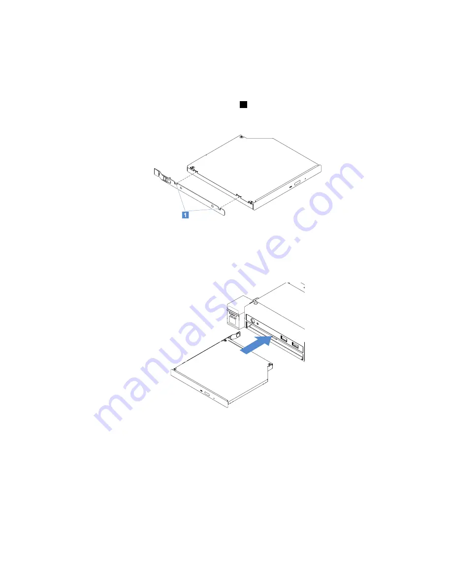
Attach the drive retention clip that you removed from the optical drive filler to the side of the
new optical drive. Ensure that the alignment pins
1
on the retention clip are aligned with the
corresponding holes in the optical drive.
Figure 40. Optical drive retention clip installation
Step 9.
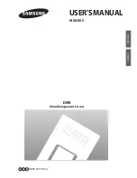
Align the optical drive with the drive bay. Then, slide the optical drive into the bay until the optical
drive clicks into place.
Figure 41. Optical drive installation
Step 10. Complete the parts replacement. See “Completing the parts replacement” on page 172.
Step 11. Reinstall the security bezel. See “Installing the security bezel” on page 92.
Removing an adapter
To remove an adapter, do the following:
Step 1.
Turn off the server. Then, disconnect all external cables and remove all peripheral devices.
Step 2.
Remove the server cover. See “Removing the server cover” on page 88.
Step 3.
Remove the PCI riser-card assembly. See “Removing the PCI riser-card assembly” on page 93.
110
Lenovo System x3250 M6 Installation and Service Guide
Summary of Contents for x3250 m6
Page 1: ...Lenovo System x3250 M6 Installation and Service Guide Machine Types 3633 and 3943 ...
Page 6: ...iv Lenovo System x3250 M6 Installation and Service Guide ...
Page 18: ...4 Lenovo System x3250 M6 Installation and Service Guide ...
Page 60: ...46 Lenovo System x3250 M6 Installation and Service Guide ...
Page 100: ...86 Lenovo System x3250 M6 Installation and Service Guide ...
Page 516: ...502 Lenovo System x3250 M6 Installation and Service Guide ...
Page 678: ...664 Lenovo System x3250 M6 Installation and Service Guide ...
Page 685: ...Taiwan Class A compliance statement Appendix E Notices 671 ...
Page 695: ......
Page 696: ......


