


7
R
P
19
R
20
P
S
N
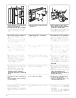
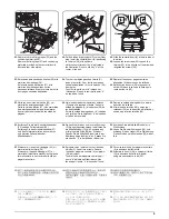
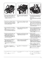
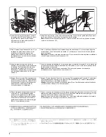
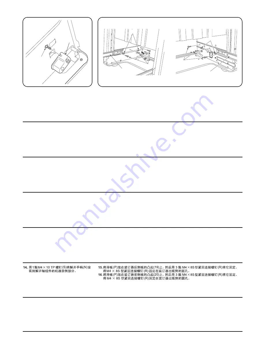
14.
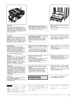
解除軸組立の機械前側部分に解除取手 (N)
を M4 × 10 TP ビス ( S ) 1 本で取り付ける。
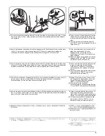
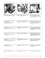
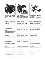
15.
スライダ (P) をフィニッシャ後側板の突起物 (19) の上に載せて M4 × 8S タイトバインドビス
(R)3 本で取り付ける。
M4 × 8S タイトバインドビス (R) の取り付けは、フィニッシャ排出側の丸穴から固定すること。
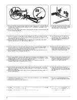
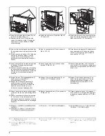
16.
スライダ (P) をフィニッシャ前側板の突起物 (20) の上に載せて M4 × 8S タイトバインドビス
(R)3 本で取り付ける。
M4 × 8S タイトバインドビス (R) の取り付けは、フィニッシャ排出側の丸穴から固定すること。
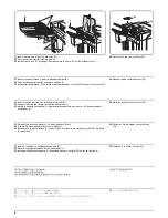
14.
Secure the release handle (N) to the release
pole assembly at the machine front side with
the M4 x 10 TP screw (S).
15.
Place the slider (P) on the projections (19) on the finisher rear side-plate and secure with three
M4 x 8S Tight Bind screws (R).
Fix the M4 x 8S Tight Bind screws (R) from the round holes on the eject side of the finisher.
16.
Place the slider (P) on the projections (20) on the finisher front side-plate and secure with three
M4 x 8S Tight Bind screws (R).
Fix the M4 x 8S Tight Bind screws (R) from the round holes on the eject side of the finisher.
14.
Fixer la poignée de dégagement (N) à
l’assemblage du pôle de dégagement, à
l’avant de la machine, à l’aide de la vis en
M4 x 10 TP (S).
15.
Placer la règle (P) sur les projections (19) figurant sur la plaque latérale arrière du retoucheur et
la fixer à l’aide des trois vis de raccordement M4 x 8S (R).
Insérer les vis de raccordement M4 x 8S (R) dans les orifices arrondis figurant sur le côté éjection
du retoucheur.
16.
Placer la règle (P) sur les projections (20) figurant sur la plaque latérale avant du retoucheur et la
fixer à l’aide des trois vis de raccordement M4 x 8S (R).
Insérer les vis de raccordement M4 x 8S (R) dans les orifices arrondis figurant sur le côté éjection
du retoucheur.
14.
Anexe la manilla de liberación (N) al
ensamble del polo de liberación en el lado
frontal de la máquina usando el tornillo de
M4 x 10 TP (S).
15.
Coloque el deslizador (P) sobre las proyecciones (19) de la placa lateral posterior y asegúrelo
con tres tornillos de cierre hermético M4 x 8S (R).
Inserte los tornillos de cierre hermético M4 x 8S (R) desde los huecos redondos ubicados en el
lado de expulsión del finalizador.
16.
Coloque el deslizador (P) sobre las proyecciones (20) de la placa lateral frontal y asegúrelo con
tres tornillos de cierre hermético M4 x 8S (R).
Inserte los tornillos de cierre hermético M4 x 8S (R) desde los huecos redondos ubicados en el
lado de expulsión del finalizador.
14.
Bringen Sie den Lösegriff (N) am
Lösestangen-Bausatz an der
Gerätevorderseite mittels der M4 x 10 TP
Schraube (S) an.
15.
Platzieren Sie den Schieber (P) auf die Vorsprünge (19) auf der hinteren Seitenplatte des
Finishers und befestigen Sie ihn mit drei M4 x 8S Verbundschrauben (R).
Befestigen Sie die M4 x 8S Verbundschrauben (R) durch die runden Löcher auf der Auswurfseite
des Finishers.
16.
Platzieren Sie den Schieber (P) auf die Vorsprünge (20) auf der vorderen Seitenplatte des
Finishers und befestigen Sie ihn mit drei M4 x 8S Verbundschrauben (R).
Befestigen Sie die M4 x 8S Verbundschrauben (R) durch die runden Löcher auf der Auswurfseite
des Finishers.
14.
Fissare l’impugnatura di rilascio (N) al
gruppo polo di rilascio sul lato anteriore della
macchina, con la vite di TP M4 x 10 (S).
15.
Posizionare il cursore (P) sulle sporgenze (19) sulla piastra laterale posteriore della finitrice e
bloccarlo con le tre viti (R) a serraggio stretto M4 x 8S.
Inserire le viti (R) a serraggio stretto M4 x 8S dai fori rotondi sul lato di espulsione della finitrice.
16.
Posizionare il cursore (P) sulle sporgenze (20) sulla piastra laterale anteriore della finitrice e bloc-
carlo con le tre viti (R) a serraggio stretto M4 x 8S.
Inserire le viti (R) a serraggio stretto M4 x 8S dai fori rotondi sul lato di espulsione della finitrice.
Summary of Contents for TASKalfa 620
Page 1: ...SERVICE MANUAL Published in August 2009 842KP112 2KPSM062 Rev 2 TASKalfa 620 820 ...
Page 4: ...This page is intentionally left blank ...
Page 10: ...This page is intentionally left blank ...
Page 144: ...2KN 2KP 1 3 106 This page is intentionally left blank ...
Page 308: ...2KN 2KP 1 5 88 This page is intentionally left blank ...
Page 412: ...2KN 2KP 2 3 60 This page is intentionally left blank ...
Page 435: ...1 1 INSTALLATION GUIDE INSTALLATION GUIDE FOR SIDE FEEDER ...
Page 442: ...INSTALLATION GUIDE FOR LARGE SIZE SIDE FEEDER ...
Page 460: ...INSTALLATION GUIDE FOR DOCUMENT FINISHER ...
Page 475: ...INSTALLATION GUIDE FOR CENTERFOLD UNIT ...
Page 490: ...INSTALLATION GUIDE FOR MULTI JOB TRAY ...
Page 501: ...INSTALLATION GUIDE FOR PUNCH UNIT ...
Page 512: ...INSTALLATION GUIDE FOR STOPPER GUIDE ...
Page 515: ...INSTALLATION GUIDE FOR PRINTING SYSTEM ...
Page 518: ...INSTALLATION GUIDE FOR SCAN SYSTEM ...
Page 520: ......
Page 521: ......


