


2KN/2KP-1
1-5-42
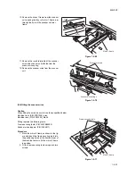
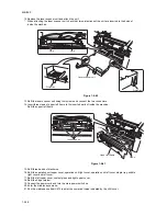
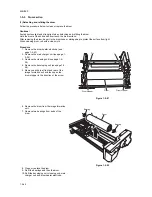
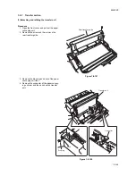
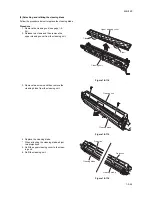
Retighten the screw.
Retighten four screws to hold the LSU.
Refit the LSU adjustment plate and contact glass.
Yes
No
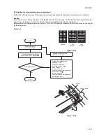
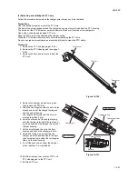
Press the start key and make
a copy at 100% magnification.
Start
End
Is the image correct?
Enter maintenance mode.
Enter 089 using the numeric keys.
Press the interrupt key.
Select 1 dot-LINE.
Press the start key.
Exit maintenance mode.
Press the stop/clear key.
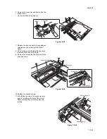
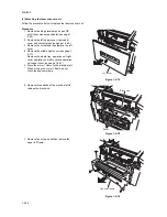
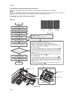
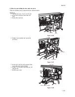
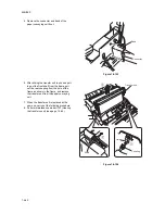
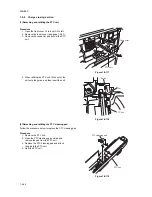
Remove the contact glass (see page 1-5-28).
Loosen four screws holding the LSU (see page 1-5-37).
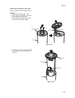
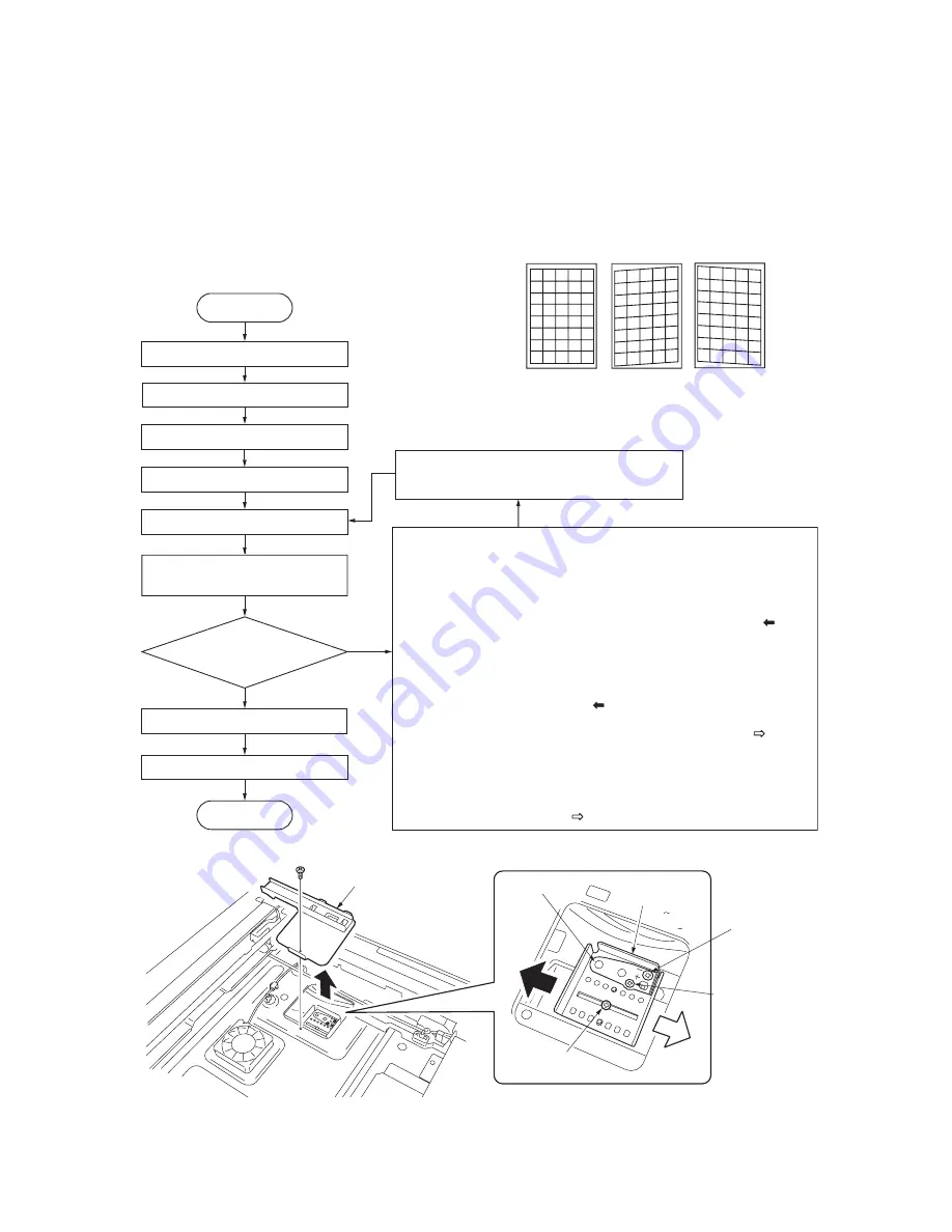
Remove the screw and then remove the LSU adjustment cover.
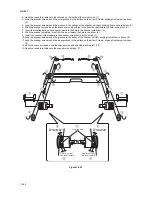
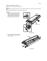
Loosen the screw and adjust the position of the LSU adjusting plate and
the position for fixing screw A, B as follows.
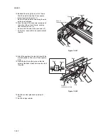
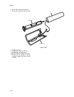
For output example 1
1. Move the LSU adjustment plate in the direction of the black arrow ( ).
2. In case adjustment is required even if the position of the LSU adjusting
plate is at the most left position and also adjusting screw A is tightened in
the hole of + marking, tighten adjustming screw A in the hole of - and then
tighten screw B.
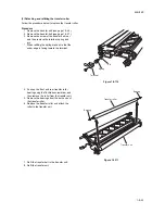
3. Move the LSU adjusting plate at the most right position and again move
it in the direction of the black arrow ( ).
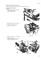
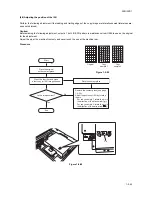
For output example 2
1. Move the LSU adjusting plate in the direction of the white arrow ( ).
2. In case adjustment is required even if the position of the LSU adjusting
plate is at the most right position and also adjusting screw A is tightened in
the hole of - marking, tighten adjusting screw A in the hole of + and then
tighten screw B.
3. Move the LSU adjusting plate at the most left position and again move it in
the direction of the white arrow ( ).
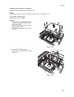
(6) Adjusting scanner image lateral squareness (reference)
Perform the following adjustment if the copy image is laterally skewed (lateral squareness not obtained).
Caution:
Perform (6-1) Adjusting the position of the laser scanner unit first and check for lateral squareness of the copy image. If
squareness is not obtained, perform (6-2) Adjusting the position of ISU (see page 1-5-43).
(6-1)Adjusting the position of the laser scanner unit
Procedure
Figure 1-5-87
Figure 1-5-88
Correct
Output
example 1
Output
example 2
LSU adjusting cover
Screw
Adjusting pin
plate
LSU adjusting
plate
Adjusting screw A
Fixed screw B
Summary of Contents for TASKalfa 620
Page 1: ...SERVICE MANUAL Published in August 2009 842KP112 2KPSM062 Rev 2 TASKalfa 620 820 ...
Page 4: ...This page is intentionally left blank ...
Page 10: ...This page is intentionally left blank ...
Page 144: ...2KN 2KP 1 3 106 This page is intentionally left blank ...
Page 308: ...2KN 2KP 1 5 88 This page is intentionally left blank ...
Page 412: ...2KN 2KP 2 3 60 This page is intentionally left blank ...
Page 435: ...1 1 INSTALLATION GUIDE INSTALLATION GUIDE FOR SIDE FEEDER ...
Page 442: ...INSTALLATION GUIDE FOR LARGE SIZE SIDE FEEDER ...
Page 460: ...INSTALLATION GUIDE FOR DOCUMENT FINISHER ...
Page 475: ...INSTALLATION GUIDE FOR CENTERFOLD UNIT ...
Page 490: ...INSTALLATION GUIDE FOR MULTI JOB TRAY ...
Page 501: ...INSTALLATION GUIDE FOR PUNCH UNIT ...
Page 512: ...INSTALLATION GUIDE FOR STOPPER GUIDE ...
Page 515: ...INSTALLATION GUIDE FOR PRINTING SYSTEM ...
Page 518: ...INSTALLATION GUIDE FOR SCAN SYSTEM ...
Page 520: ......
Page 521: ......


