


2KN/2KP
2-1-9
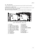
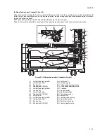
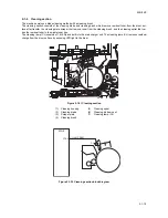
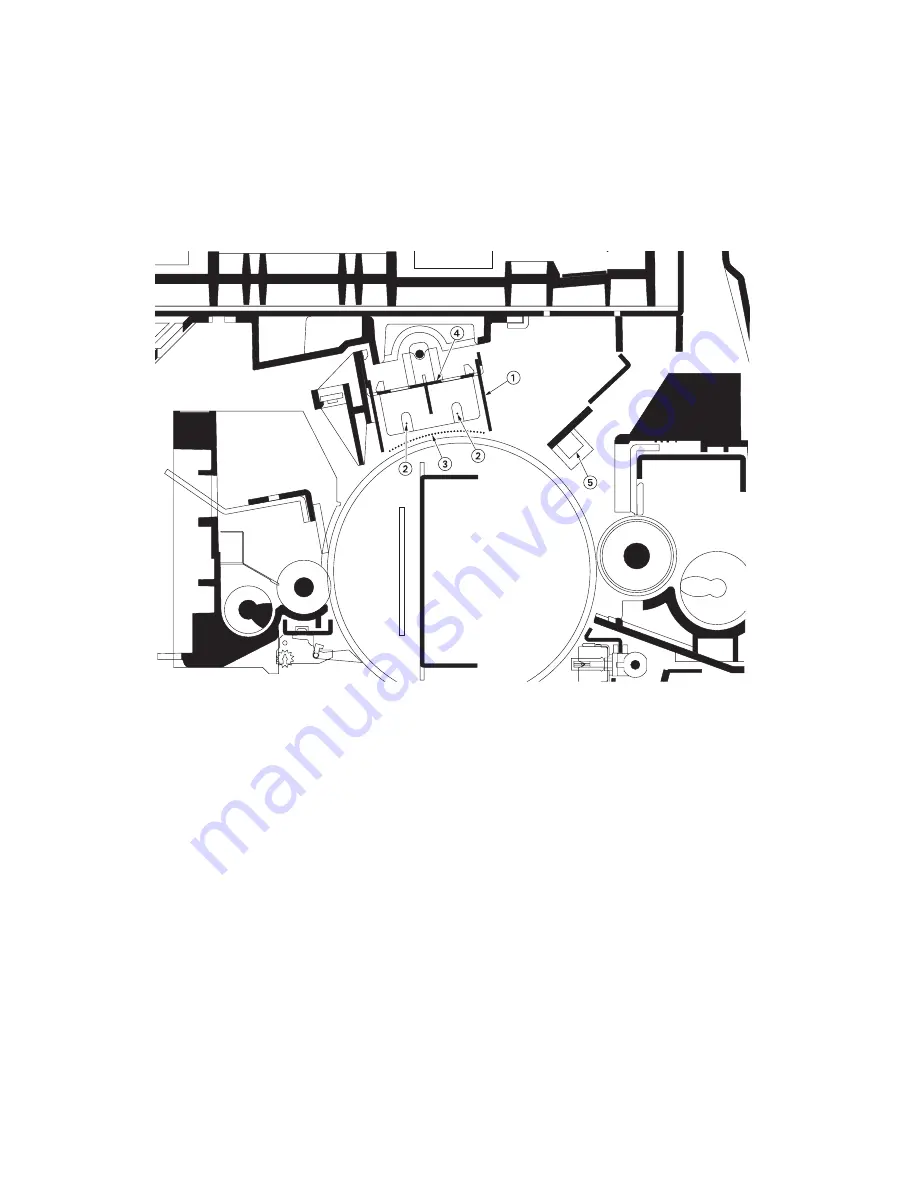
2-1-2 Main charger section
The main charging section consists of the main charger unit, drum, potential sensor and so on. The drum is electrically
charged uniformly by means of a grid to form a latent image on the surface.
The potential sensor (DPS) reads the drum surface potential and corrects surface potential.
The main charger unit has the main charger cleaning motor (CLM), main charger cleaning pad for automatic cleaning of
the charger wire.
The drum heater (DRH) inside the drum is turned on and off based on changes in ambient temperature and humidity to
stabilize the image quality.
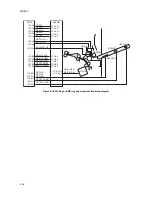
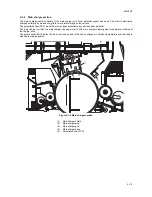
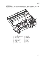
Figure 2-1-9 Main charger section
(1)
Main charger shield
(2)
Main charger wire
(3)
Main charger grid
(4)
Main charger base
(5)
Potential sensor (PTS)
Summary of Contents for TASKalfa 620
Page 1: ...SERVICE MANUAL Published in August 2009 842KP112 2KPSM062 Rev 2 TASKalfa 620 820 ...
Page 4: ...This page is intentionally left blank ...
Page 10: ...This page is intentionally left blank ...
Page 144: ...2KN 2KP 1 3 106 This page is intentionally left blank ...
Page 308: ...2KN 2KP 1 5 88 This page is intentionally left blank ...
Page 412: ...2KN 2KP 2 3 60 This page is intentionally left blank ...
Page 435: ...1 1 INSTALLATION GUIDE INSTALLATION GUIDE FOR SIDE FEEDER ...
Page 442: ...INSTALLATION GUIDE FOR LARGE SIZE SIDE FEEDER ...
Page 460: ...INSTALLATION GUIDE FOR DOCUMENT FINISHER ...
Page 475: ...INSTALLATION GUIDE FOR CENTERFOLD UNIT ...
Page 490: ...INSTALLATION GUIDE FOR MULTI JOB TRAY ...
Page 501: ...INSTALLATION GUIDE FOR PUNCH UNIT ...
Page 512: ...INSTALLATION GUIDE FOR STOPPER GUIDE ...
Page 515: ...INSTALLATION GUIDE FOR PRINTING SYSTEM ...
Page 518: ...INSTALLATION GUIDE FOR SCAN SYSTEM ...
Page 520: ......
Page 521: ......


