

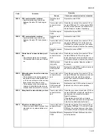


2KN/2KP
1-4-38
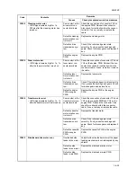
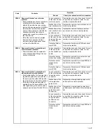
C4000
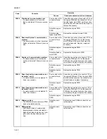
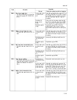
Polygon motor synchronization prob-
lem
• The revolution does not reach the sta-
ble speed within 20 s of the START
signal.
Poor contact in the
polygon motor con-
nector terminals.
Reinsert the connector. Also check for conti-
nuity within the connector cable. If none,
remedy or replace the cable.
Defective polygon
motor.
Replace the laser scanner unit (see page 1-
5-36).
Defective engine
PWB.
Check if 24 V DC is supplied to YC17-1 on
the engine PWB. If not, replace the engine
PWB.
C4010
Polygon motor steady-state problem
• The polygon motor rotation is not sta-
ble for 5 s after the polygon motor rota-
tion has been stabilized.
Poor contact in the
polygon motor con-
nector terminals.
Reinsert the connector. Also check for conti-
nuity within the connector cable. If none,
remedy or replace the cable.
Defective polygon
motor.
Replace the laser scanner unit (see page 1-
5-36).
Defective engine
PWB.
Check if 24 V DC is supplied to YC17-1 on
the engine PWB. If not, replace the engine
PWB.
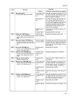
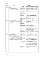
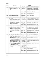
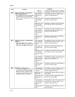
C4100
BD initialization (A) problem
• When power is turned on, only laser A
is output and ASIC of main PWB
detects a BD error for 2000 ms.
Defective laser
scanner unit.
Replace the laser scanner unit (see page 1-
5-36).
Defective main
PWB.
Replace the main PWB and check for cor-
rect operation.
Poor contact in
connector termi-
nals.
Check the connection of connector YC8 on
the main PWB. Repair or replace if neces-
sary.
C4110
BD initialization (B) problem
• When power is turned on, only laser B
is output and ASIC of main PWB
detects a BD error for 2000 ms.
Defective laser
scanner unit.
Replace the laser scanner unit (see page 1-
5-36).
Defective main
PWB.
Replace the main PWB and check for cor-
rect operation.
Poor contact in
connector termi-
nals.
Check the connection of connector YC8 on
the main PWB and the continuity across the
connector terminals. Repair or replace if
necessary.
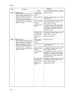
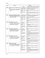
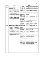
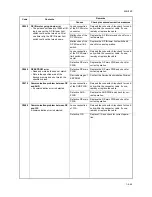
C4120
BD initialization (C) problem
• When power is turned on, only laser C
is output and ASIC of main PWB
detects a BD error for 2000 ms.
Defective laser
scanner unit.
Replace the laser scanner unit (see page 1-
5-36).
Defective main
PWB.
Replace the main PWB and check for cor-
rect operation.
Poor contact in
connector termi-
nals.
Check the connection of connector YC8 on
the main PWB and the continuity across the
connector terminals. Repair or replace if
necessary.
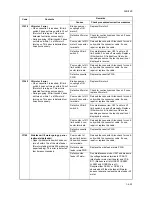
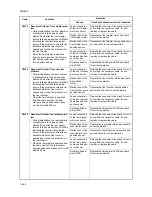
C4200
BD steady-state problem
• ASIC of the main PWB detects a BD
error A for 4000 ms after the polygon
motor rotation has been stabilized.
Defective laser
diode.
Replace the laser scanner unit (see page 1-
5-36).
Defective polygon
motor.
Replace the laser scanner unit (see page 1-
5-36).
Defective main
PWB.
Replace the main PWB and check for cor-
rect operation.
Poor contact in
connector termi-
nals.
Check the connection of connector YC8 on
the main PWB and the continuity across the
connector terminals. Repair or replace if
necessary.
Code
Contents
Remarks
Causes
Check procedures/corrective measures
Summary of Contents for TASKalfa 620
Page 1: ...SERVICE MANUAL Published in August 2009 842KP112 2KPSM062 Rev 2 TASKalfa 620 820 ...
Page 4: ...This page is intentionally left blank ...
Page 10: ...This page is intentionally left blank ...
Page 144: ...2KN 2KP 1 3 106 This page is intentionally left blank ...
Page 308: ...2KN 2KP 1 5 88 This page is intentionally left blank ...
Page 412: ...2KN 2KP 2 3 60 This page is intentionally left blank ...
Page 435: ...1 1 INSTALLATION GUIDE INSTALLATION GUIDE FOR SIDE FEEDER ...
Page 442: ...INSTALLATION GUIDE FOR LARGE SIZE SIDE FEEDER ...
Page 460: ...INSTALLATION GUIDE FOR DOCUMENT FINISHER ...
Page 475: ...INSTALLATION GUIDE FOR CENTERFOLD UNIT ...
Page 490: ...INSTALLATION GUIDE FOR MULTI JOB TRAY ...
Page 501: ...INSTALLATION GUIDE FOR PUNCH UNIT ...
Page 512: ...INSTALLATION GUIDE FOR STOPPER GUIDE ...
Page 515: ...INSTALLATION GUIDE FOR PRINTING SYSTEM ...
Page 518: ...INSTALLATION GUIDE FOR SCAN SYSTEM ...
Page 520: ......
Page 521: ......


